 0
0
Deepcool Quanta DQ1250 1250 W Review
Voltage Regulation, Hold-up Time & Inrush Current »A Look Inside & Component Analysis
Before reading this page, we strongly suggest a look at this article, which will help you understand the internal components of a PSU much better. Our main tool for the disassembly of the PSU is a Thermaltronics TMT-9000S soldering and rework station. It is of extreme quality and is equipped with a matching de-soldering gun. With such equipment in hand, breaking apart every PSU is like a walk in the park!


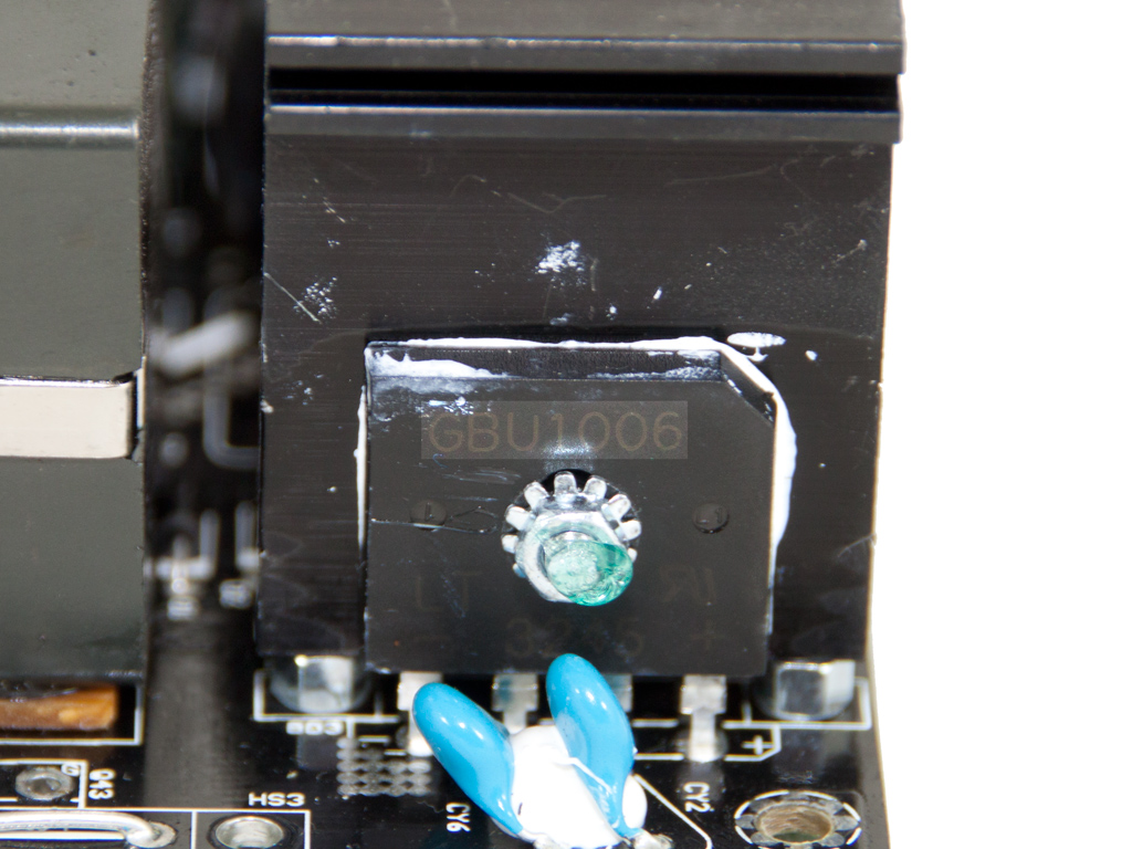
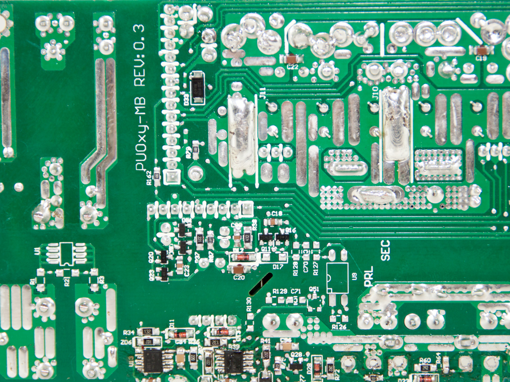
The green transformers are easy tell-tale signs when it comes to identifying the OEM, Channel Well Technology. Although the platform counts as some years in production, it can still be considered cutting edge because it uses an interleaved APFC and an LLC converter for loss-less switching in the primary side. The secondary side uses DC-DC converters that are directly installed to the modular PCB, which restricts energy losses nicely. To clear the view for you, we removed the APFC's heatsinks on the primary side.
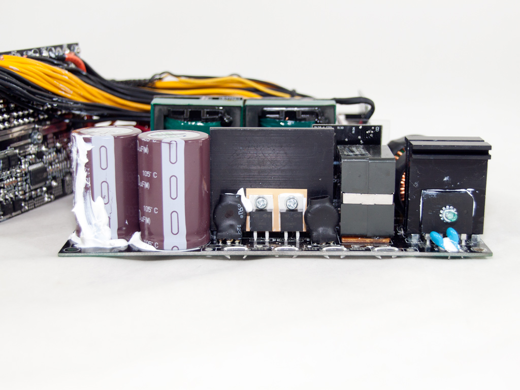
The first part of the transient filtering stage starts right at the AC receptacle, with one X and two Y caps. On the main PCB are the other transient-filtering components, two pairs of Y caps (with the second pair right behind the bridge rectifiers), a pair of X cap, two CM chokes, and an MOV. All in all, the transient filter is complete.


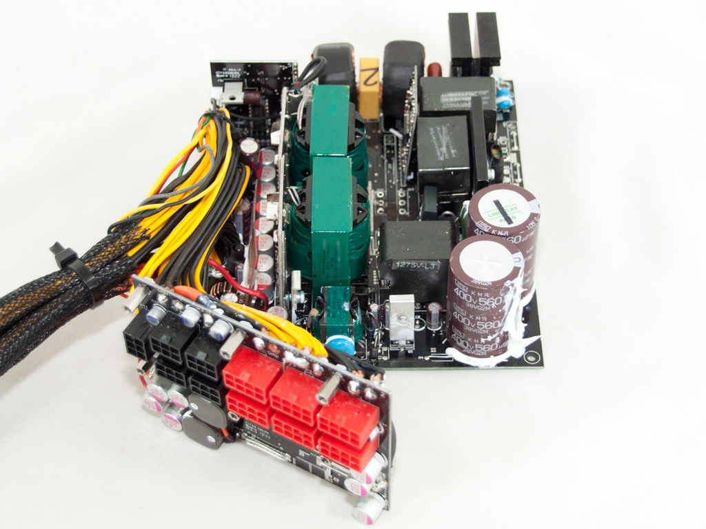
Three parallel bridge rectifiers are used. Their model number is GBU1006, and they can handle up to 30A!


The PSU uses an interleaved PFC circuit, which means that there are in fact two APFC converters which work in parallel, with a phase difference amongst them. This minimizes input/output current ripple and lowers conduction losses, which increases efficiency and doubles the effective switching frequency. Each APFC converter uses an IPW60R099CP mosfet and a CREE C3D10060 boost diode. Next to each boost diode is a current-sense inductor in heat-shrink tubing; there is one for each APFC converter. There are two Nippon Chemi-Con bulk caps (400 V, 560 µF each or 1120 µF combined, 105°C, KMR series).
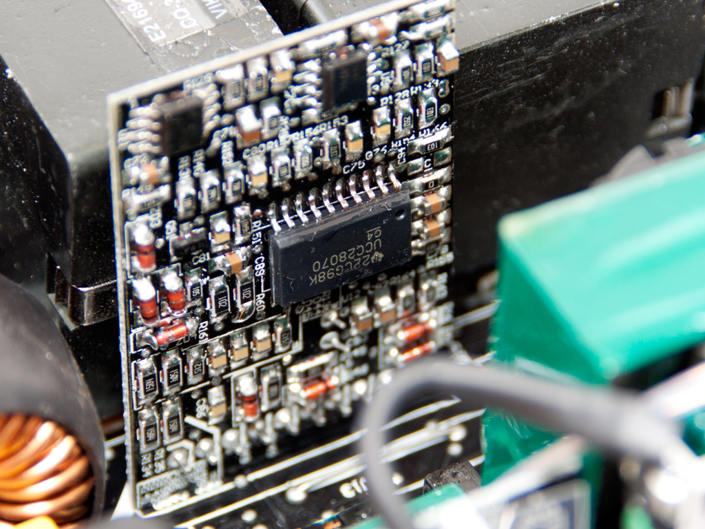
The Interleaving Continuous Conduction Mode PFC controller is a UCC28070.


The LLC resonant converter is combined with a full bridge topology where the primary switches are four SiHG30N60E mosfets to minimize switching losses, which increases efficiency.

The LLC resonant controller is a Champion CM6901 IC.

There are two parallel main transformers, and CWT thankfully changed the location of the thermistor responsible for fan speed by moving it away from the main transformers and onto the PCB that holds the +12V fets, which has the thermistor provide much more accurate readings as these fets are stressed more and need constant monitoring. The DQ1250's fan as such actually engaged in time to effectively protect sensitive components like caps and fets, which is contrary to the Toughpower 1275 W where the fan engaged incredibly late.


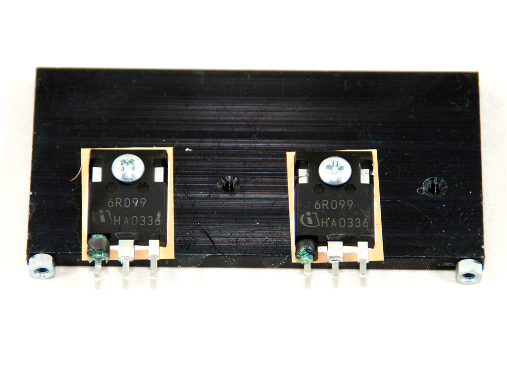
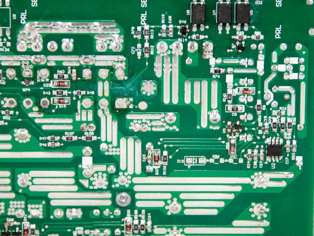
The secondary side utilizes a synchronous design. All mosfets responsible for regulating both +12V rails are installed on two vertical PCBs that are very close to the main transformers. Every PCB holds six IPD031N06L mosfets, so there are a total of 12 mosfets for the +12V rails. The secondary side mostly utilizes polymer caps for filtering purposes, which boosts the units reliability and longevity. The few electrolytic caps used in the secondary side are provided by Chemi-Con.

We would like to see heat shrinks on all of the cables above.


All protections are handled by a SITI PS229 soldered to a vertical PCB in the secondary side. It, strangely enough, only supports one +12V OCP channel, so OCP for the second +12V rail has probably been implemented in another way.


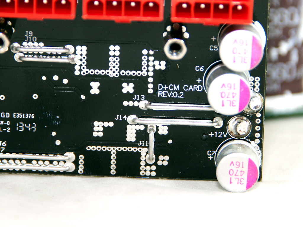


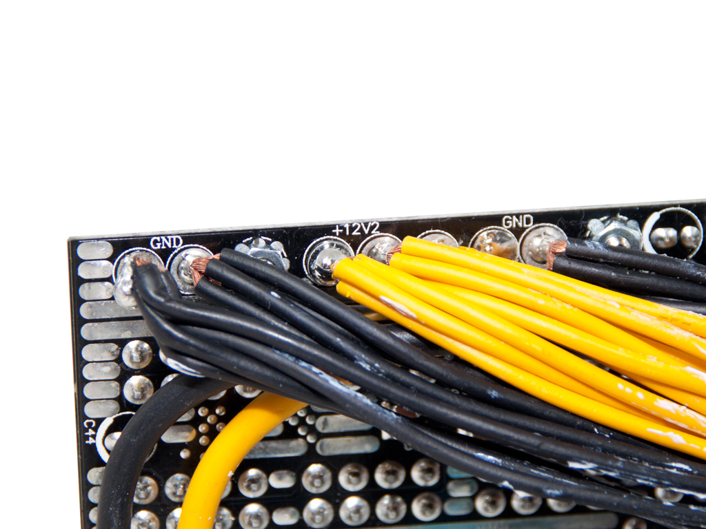
The modular PCB's primary side holds several polymer caps by Duratech and Enesol, along with two inductors for the filtering and rectification of the two aforementioned rails. We also noticed a thick wire that transfers 3.3V to the modular socket at the top on the solder side of the same PCB. There apparently wasn't enough room for a PCB trace and 3.3V lead there, which had CWT use this wire. This wire actually reduces the advantage of having the 3.3V VRM on the modular PCB as it doesn't keep the wires which transfer power to a minimum in order to restrict energy losses.

The VRMs that generate the minor rails are on the modular PCB, which minimizes power losses on those rails. In total, four M3004D and four M3006D mosfets respectively rectify the 3.3V and 5V rails. Their common PWM controller is an APW7159.
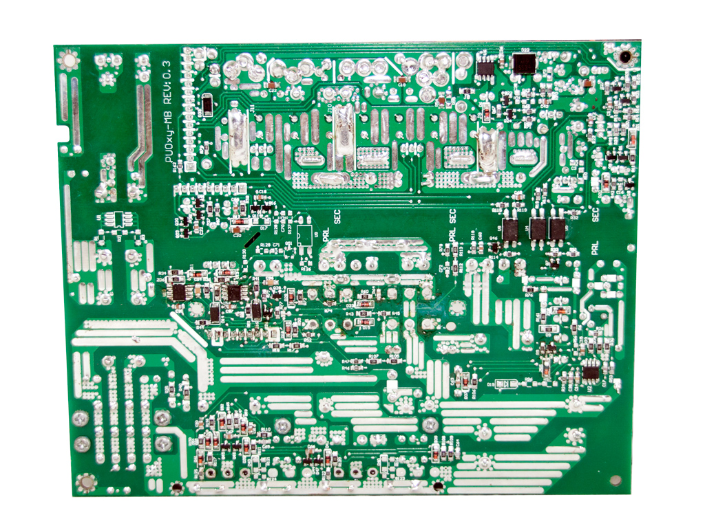


Soldering quality of our sample wasn't the best we have ever seen from CWT, and we noticed many rather sloppy hand-soldered joints.
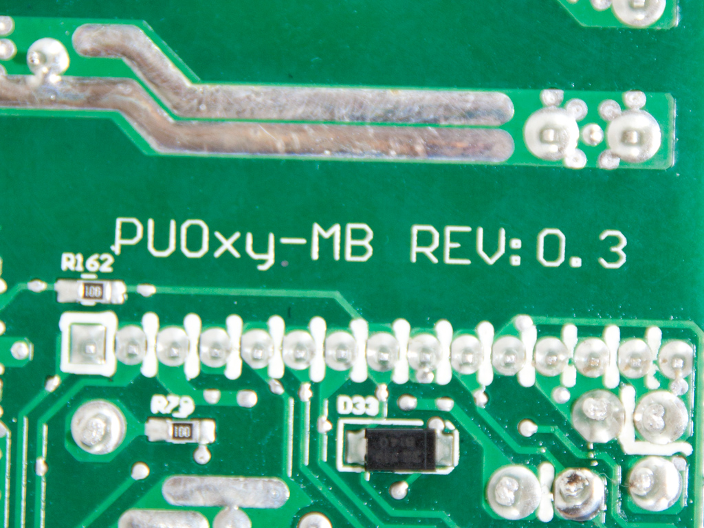
CWT named this platform PUO.


According to Yate Loon, the fan with model number D14BM-12 has a maximum RPM of 1400 RPM, but our trusty and incredibly accurate tachometer measured 2000 RPM, and amperage (0,7 A) is actually pretty high for 1400 RPM. However, Yate Loon's fan never exceeded 1550 RPM in our tests, which resulted in tolerable noise level for a 1.25 kW PSU.
Apr 24th, 2024 14:51 EDT
change timezone
Latest GPU Drivers
New Forum Posts
- GTX 1070 Ti - TDP Issues - Always Power Throttling (0)
- What are you playing? (20523)
- Youtube layout has changed, how to go back ? (16)
- How are MX330 and İ5 1135G7 ? (8)
- Is there a technical reason that Windows 11 doesn't have built into it battery charge limitation? (40)
- Realtek Modded Audio Driver for Windows 10/11 - Only for HDAUDIO (5690)
- I7-8750H + GTX 1050ti Laptop drops performance periodically (5)
- Aida64 cache mem OC (6)
- Official Board Game Discussion (20)
- Rare GPUs / Unreleased GPUs (1873)
Popular Reviews
- Fractal Design Terra Review
- Thermalright Phantom Spirit 120 EVO Review
- Corsair 2000D Airflow Review
- Minisforum EliteMini UM780 XTX (AMD Ryzen 7 7840HS) Review
- ASUS GeForce RTX 4090 STRIX OC Review
- NVIDIA GeForce RTX 4090 Founders Edition Review - Impressive Performance
- ASUS GeForce RTX 4090 Matrix Platinum Review - The RTX 4090 Ti
- MSI GeForce RTX 4090 Suprim X Review
- MSI GeForce RTX 4090 Gaming X Trio Review
- Gigabyte GeForce RTX 4090 Gaming OC Review
Controversial News Posts
- Sony PlayStation 5 Pro Specifications Confirmed, Console Arrives Before Holidays (116)
- NVIDIA Points Intel Raptor Lake CPU Users to Get Help from Intel Amid System Instability Issues (106)
- AMD "Strix Halo" Zen 5 Mobile Processor Pictured: Chiplet-based, Uses 256-bit LPDDR5X (101)
- US Government Wants Nuclear Plants to Offload AI Data Center Expansion (98)
- Windows 10 Security Updates to Cost $61 After 2025, $427 by 2028 (84)
- Developers of Outpost Infinity Siege Recommend Underclocking i9-13900K and i9-14900K for Stability on Machines with RTX 4090 (84)
- TechPowerUp Hiring: Reviewers Wanted for Motherboards, Laptops, Gaming Handhelds and Prebuilt Desktops (78)
- Intel Realizes the Only Way to Save x86 is to Democratize it, Reopens x86 IP Licensing (70)