 0
0
Enermax MAXREVO 1500 W Review
Voltage Regulation, Hold-up Time & Inrush Current »A Look Inside & Component Analysis
Before reading this page, we strongly suggest a look at this article, which will help you understand the internal components of a PSU much better.


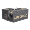
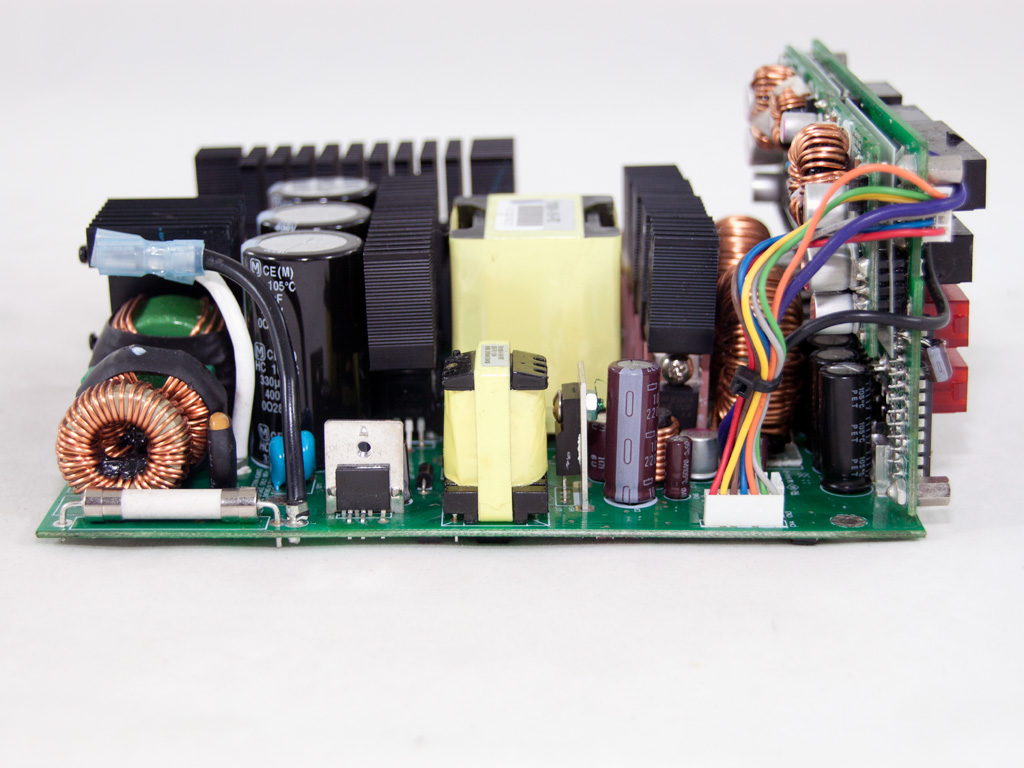
The PSU uses a modern platform with a very clean and, at the same time, unique design. The whole idea behind this design was to bring the secondary side as close as possible to the modular panel in order to minimize energy losses since the DC outputs have to travel smaller distances that way, which, at the same time, greatly boosts efficiency. ENERMAX's specifically designed heatsinks also allow for increased airflow, although most of them are installed horizontally to the air flow. The DC-DC converters on the secondary side are installed right on the modular PCB to provide their outputs to the modular sockets directly.
There is a complete line filter at the AC input of the PSU - a Yunpen Y015T1 that includes one X cap, two Y caps, and a CM choke. The other components of the transient filtering stage, here three CM chokes, one X cap, and two Y caps along with an MOV, reside on the main PCB.

Thankfully, the main PCB is connected to the on/off switch through two crimp terminals, something that makes its removal a piece of cake.

There is only a single rectifying bridge (GBJ 20J) which can, however, handle up to 20 A of current, which means it will easily deal with the max capacity of this unit.


The APFC utilizes four FQA 24N50 fets along with the necessary boost diode.


The three parallel caps (330μF, 400V, 105°C, HC series) are provided by Panasonic/Matsushita. Their combined capacity is 990μF, which is kind of low if we take into account the max power that this PSU can deliver.

The heatsink in front of the hold-up caps holds the main switchers: four MDF18N50 mosfets configured in a Zero Voltage Switching (ZVS) Phase-Shifted Full-Bridge topology. This is a state of the art topology that offers the best efficiency possible since it minimizes energy losses on the main switches.

The NTC thermistor, responsible for protection against large inrush currents and the corresponding relay that isolates it from the circuit once the start-up phase finishes, is located between the APFC and the primary heatsinks.


These two vertical daughter-boards house some interesting components. On the right board resides the PFC controller, an ICE2PCS01, and an LM393 voltage comparator that assists in overvoltage and undervoltage protection. On the left board resides a UCC28950 IC, a controller responsible for the main switchers. The second IC on the left board is a UCC27324, a high speed low-side power mosfet driver.

The main transformer looks small but is, thanks to its high density, able to easily cope with the demands of this powerful platform. On the front of the main transformer resides the secondary heatsink that holds all +12V rectifying fets; six IRFB3004 in total.


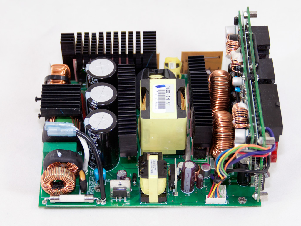
Two large toroidal chokes are used for the rectification of +12V, and we meet an array of Rubycon filtering caps (1500μF, 16V, 105°C, ZLK series) right in front of them. The current shunt resistors, located on the solder side of the modular PCB, can also be seen from this angle.
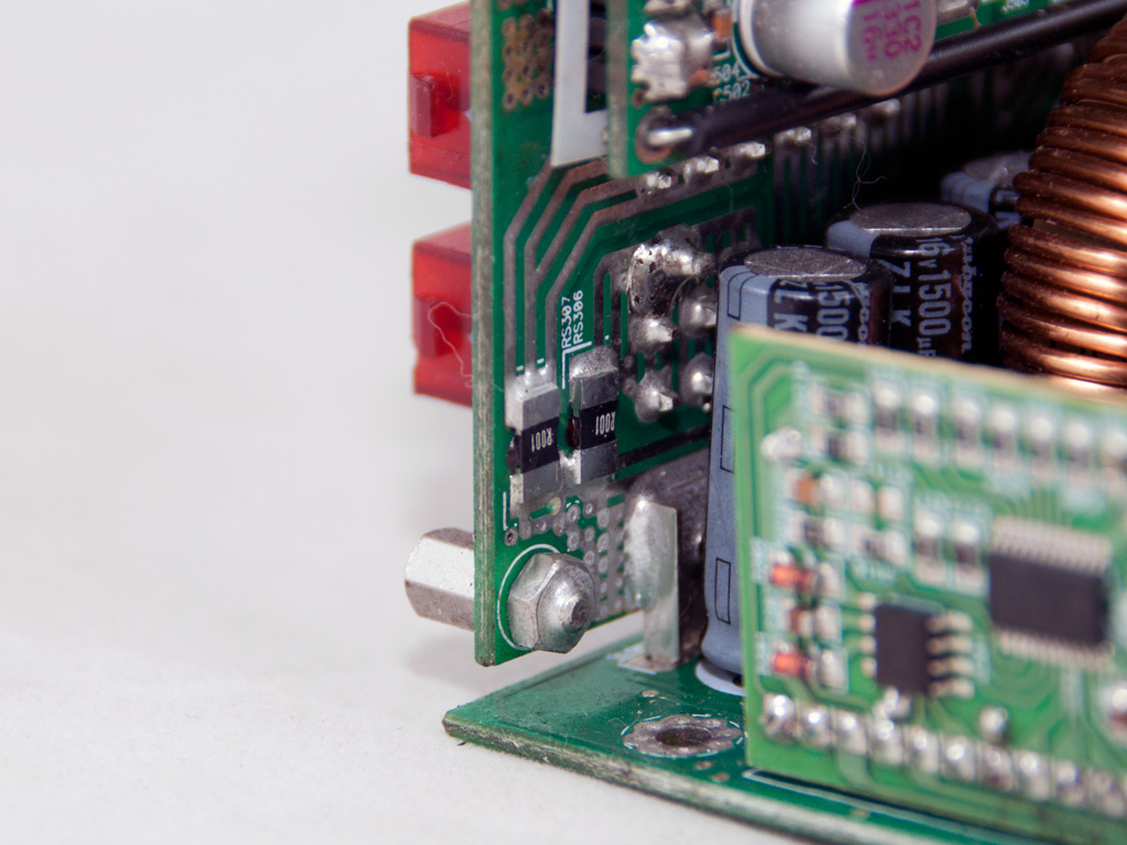
The +12V rails are delivered to the modular PCB through many copper bus bars Enermax has dubbed copper-bridge transmission array. Following this method greatly reduces voltage and, thus, energy drops, especially at high loads.


The VRMs that generate the minor rails are located on the modular PCB. In each one we find an APW7073A PWM controller and four APM2556N mosfets.

The supervisor IC, a SITI PS238, is soldered onto the modular PCB. It provides OCP for up to six +12V rails, which matches the specifications of this unit.
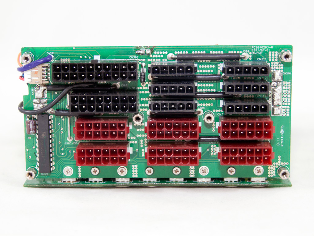

The modular PCB isn't equipped with any filtering caps for some extra ripple suppression. Apparently, this wasn't considered necessary.


A TOPSwitch-JX TOP265 integrated off-line switcher controls the 5VSB circuit and is responsible for its high efficiency in standby.


Soldering quality is impeccable and easily meets the competition in this high-end category. Enermax took some large steps forward in this area within the last couple of years, and we are very happy to look at such high-quality PCBs. Lora, as you can see, signed the PCB!

The cooling fan carries Enermax's logo and its model number is ED142512S-DA (139mm, 12V, 0.6A, 900 - 2000rpm). It features twister bearings for increased lifespan and is quiet enough at low RPM.
Apr 26th, 2024 03:05 EDT
change timezone
Latest GPU Drivers
New Forum Posts
- Best SSD for system drive (82)
- What phone you use as your daily driver? And, a discussion of them. (1484)
- What's your latest tech purchase? (20342)
- AMD RX 7000 series GPU Owners' Club (1087)
- im new to throttelstop and i think i messed it up by copying others any hints would be very much aprreciated (3)
- Horizontal black lines popping up on my screen? (4)
- Which new games will you be buying? (316)
- Alphacool CORE 1 CPU block - bulging with danger of splitting? (20)
- Black screen after muting (5)
- What are you playing? (20530)
Popular Reviews
- Fractal Design Terra Review
- Thermalright Phantom Spirit 120 EVO Review
- Corsair 2000D Airflow Review
- ASUS GeForce RTX 4090 STRIX OC Review
- NVIDIA GeForce RTX 4090 Founders Edition Review - Impressive Performance
- ASUS GeForce RTX 4090 Matrix Platinum Review - The RTX 4090 Ti
- MSI GeForce RTX 4090 Suprim X Review
- Gigabyte GeForce RTX 4090 Gaming OC Review
- MSI GeForce RTX 4090 Gaming X Trio Review
- MSI GeForce RTX 4090 Suprim Liquid X Review
Controversial News Posts
- Sony PlayStation 5 Pro Specifications Confirmed, Console Arrives Before Holidays (117)
- Windows 11 Now Officially Adware as Microsoft Embeds Ads in the Start Menu (112)
- NVIDIA Points Intel Raptor Lake CPU Users to Get Help from Intel Amid System Instability Issues (106)
- AMD "Strix Halo" Zen 5 Mobile Processor Pictured: Chiplet-based, Uses 256-bit LPDDR5X (101)
- US Government Wants Nuclear Plants to Offload AI Data Center Expansion (98)
- AMD's RDNA 4 GPUs Could Stick with 18 Gbps GDDR6 Memory (88)
- Developers of Outpost Infinity Siege Recommend Underclocking i9-13900K and i9-14900K for Stability on Machines with RTX 4090 (85)
- Windows 10 Security Updates to Cost $61 After 2025, $427 by 2028 (84)