 16
16
Gigabyte GA-P67A-UD4-B3 Review
BIOS Walkthrough »The Board - A Closer Look
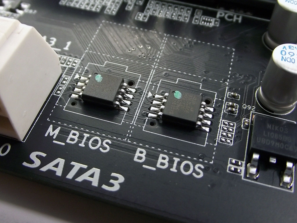
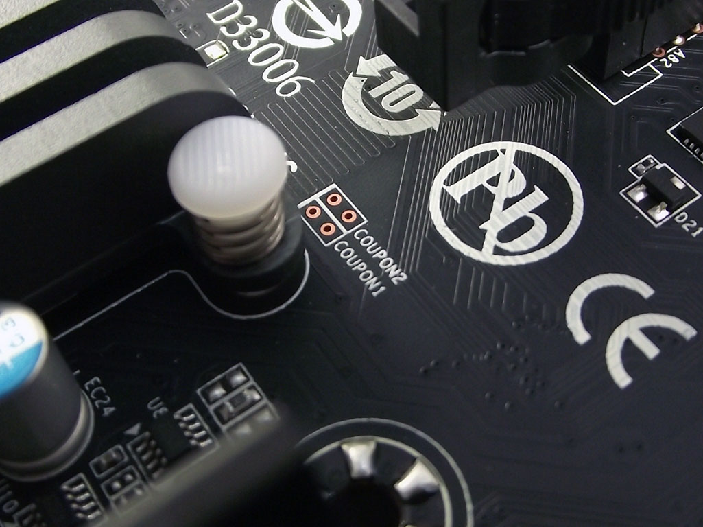
One of the most critical components that affects clocking, is, of course, the BIOS. Gigabyte, for a long time standing, has equipped many of their products with the now familiar "DualBios", featuring two separate BIOS chips, allowing for a guaranteed boot when attempting to push things to the uppermost limits. If a changed setting leads to an unsuccessful boot, the board can boot from the backup bios, allowing settings to be adjusted back so that the board can boot properly. Gigabyte has also been known to hide some advanced settings that are displayed with a combination of button presses, so when we saw space for two headers labeled "COUPON" next to the chipset cooler of the P67A-UD4-B3, we were curious as to what functionality these might provide. Unfortunately, without pins fitted to the holes, not much use of them can be made.
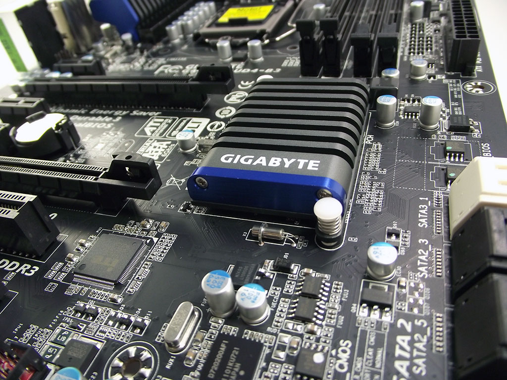
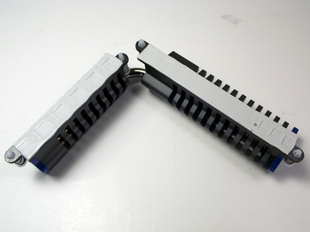
Speaking of the chipset cooler, Gigabyte's new aesthetics provide the P67A-UD4-B3 with a nice small grey cooler reminiscent of, well, a radiator. A small blue-coloured plate is attached to the bottom edge of the cooler just under the Gigabyte logo, leaving a familiar touch on this highly-effective unit. The design is such to take advantage of lateral airflow, and the theme is carried on to the MOSFET cooler that is wrapped around the CPU socket. Due to the nature of the thermal interface of the chipset cooler, we chose to not remove it, but the MOSFET cooler on the other hand, was quickly removed due to the simple attachment mechanism offered by the plastic clips used to secure it to the board itself. Upon inspection of the MOSFET cooler we noticed very little contact on one end of the cooler, caused by uneven component height. While not necessarily something to be concerned about, we did take some extra time when replacing this cooler to ensure the best contact possible.
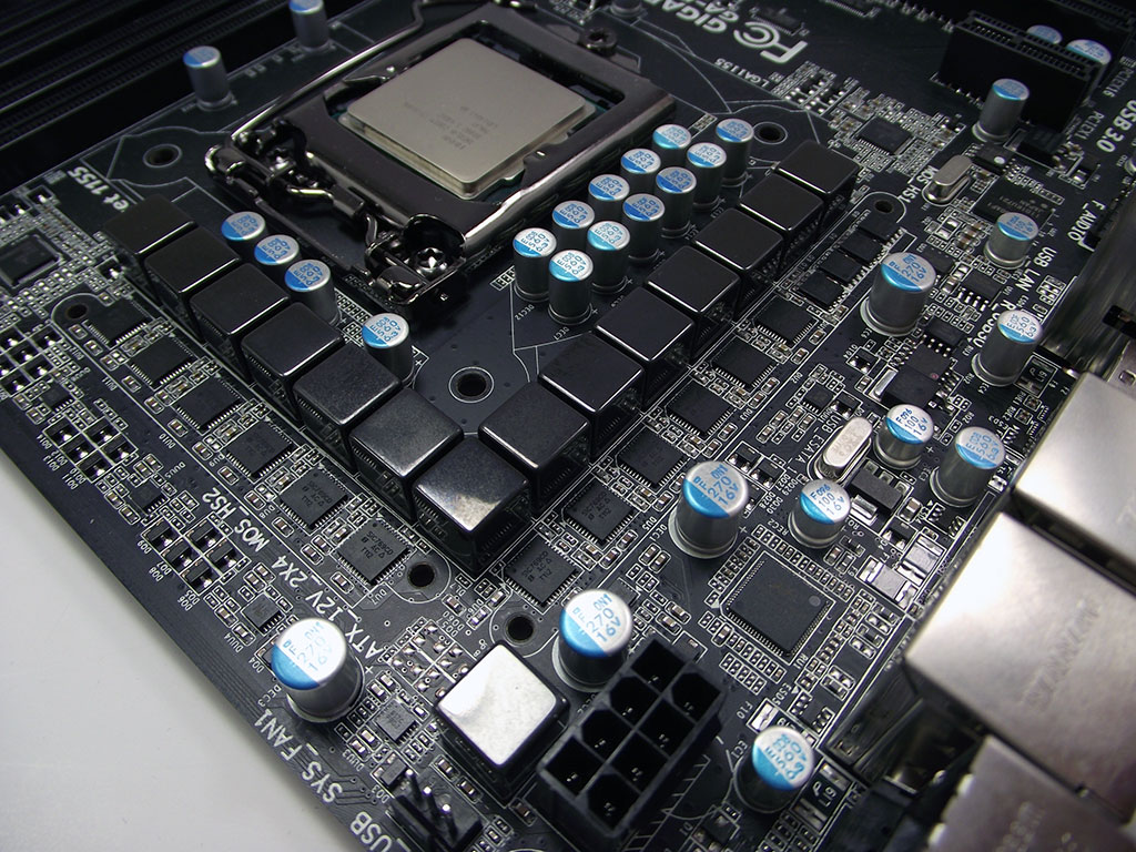
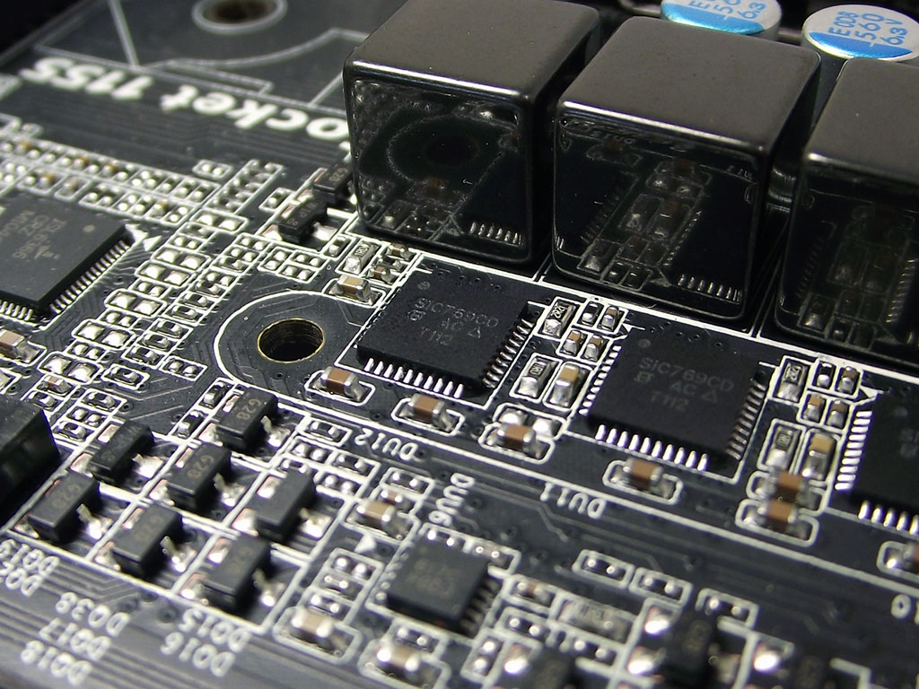
Removing the MOSFET cooler provided the opportunity to examine the board's VRM circuitry closely. Featuring DRMOS technology, which integrates many separate parts into one "Super IC", the Gigabyte P67A-UD4-B3 features 12 full phases for the CPU proper, with two additional phases for memory/System Agent control. Each of the 14 phases is terminated by a highly reflective metal-encased ferrite core choke, a small thing that really lends towards this board's high-end feel. The single DIMM power phase features a matching choke to the CPU power phases, and in fact, we find that the all of the chokes around the board's surface have received this same treatment, which really helps tie Gigabyte's new color scheme into something that quite nearly approaches being a work of art.
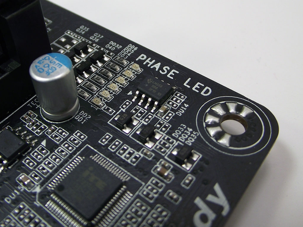

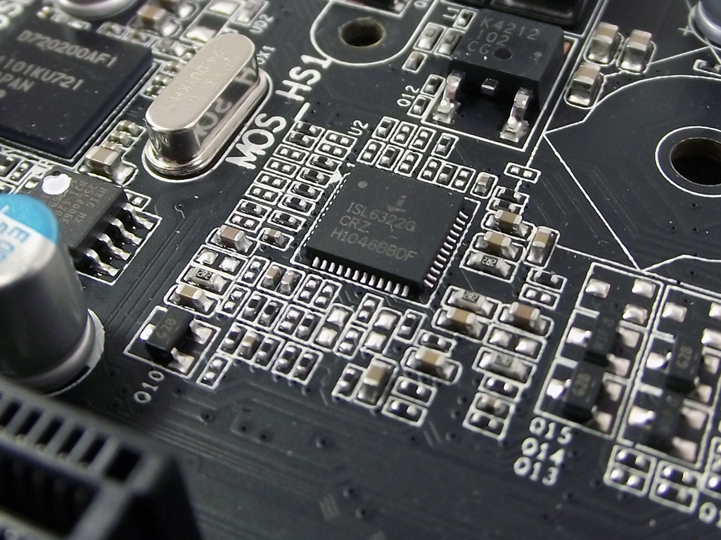
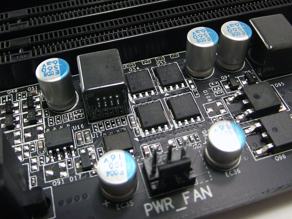
There are several components in various places around the socket that make up the Gigabyte P67A-UD4-B3's complete VRM design. Featuring Gigabyte's own "Dynamic Energy Saver" technology, the first bit is a software-controlled interface, mated with a series of LEDs, that controls and indicates which phases are in operation. However, it's worth noting that there is only six LEDs, yet 12 phases. As noted earlier, this is due to the "Dual Engine" design Gigabyte has employed, with each "engine" comprising of six phases each controlled by the same interface. The "Dual Engine" is controlled by the ISL6366, which also supplies control for System Agent voltage, while the dual-phase memory-control VRM is operated via the ISL6322G controller. Together, with the D.E.S. software provided on the driver disc, the VRM solution provided for the P67A-UD4-B3 features full-on clean power for those that need it, as well as a dynamic loading scheme for those primarily concerned with saving on overall power consumption.
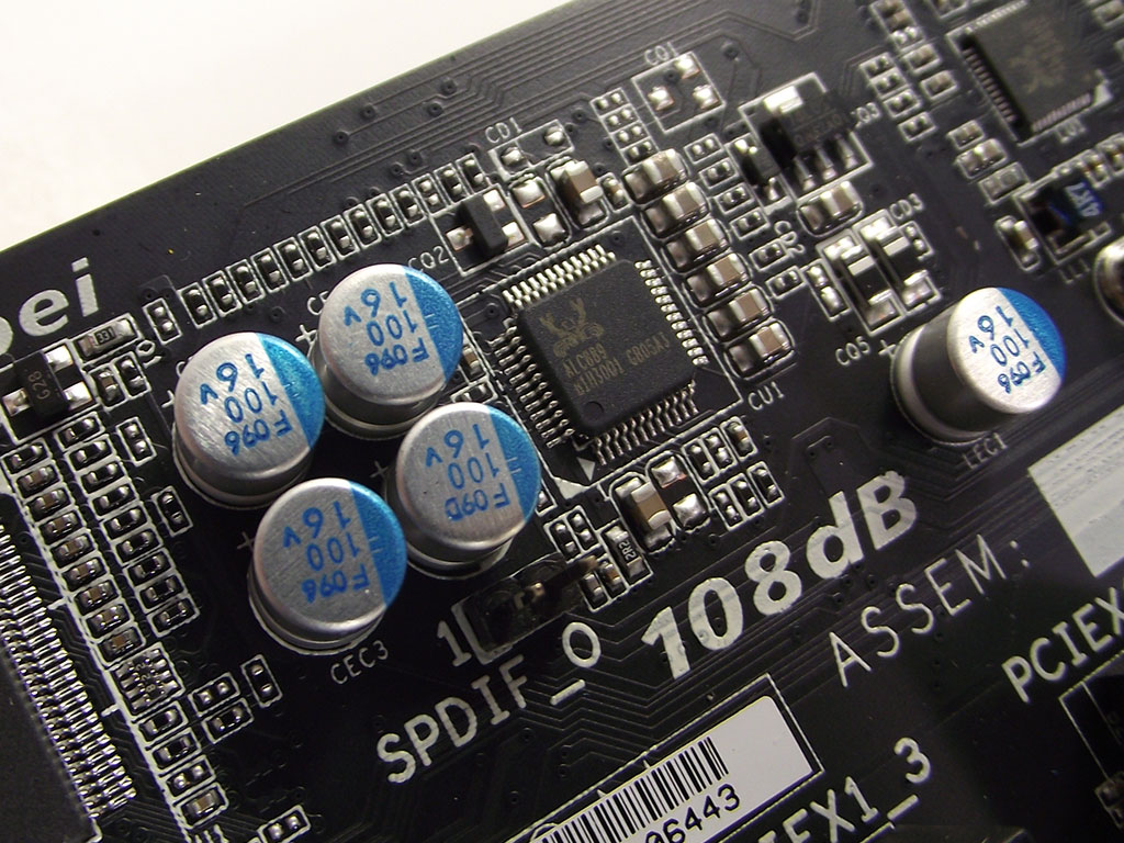
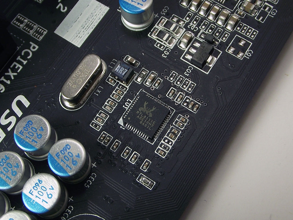
Both audio and LAN support are provided by Realtek-provided parts, with the RTL8111E PCIe Ethernet controller being a commonly used part throughout the entire industry. The ALC889 audio CODEC, on the other hand, is not as widely used, and does boast some specific features, like Blu-Ray audio decoding, not seen elsewhere. This CODEC is the reason we find the Dolby case badge with the other box candy, and its reputation and functionality is something we personally have grown quite fond of.
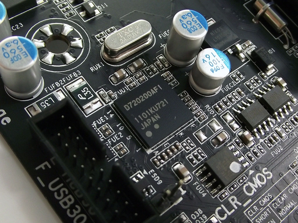
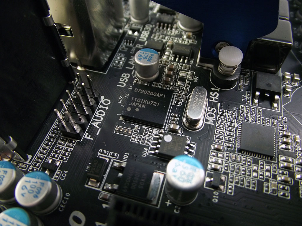
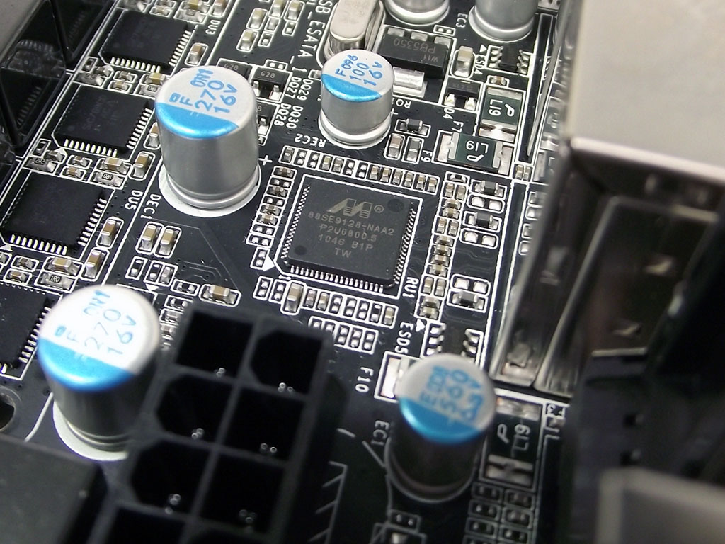
USB 3.0 support is provided, quite naturally, by the standard NEC/Renesas controller, of which there are two separate controllers, one near the bottom edge of the board, and the other near the rear I/O panel. This revised chipset provides better power savings when idle versus the previous incarnation of the same chipset, a choice we are very glad Gigabyte made. Right above the rear controller we find the Marvell 88SE9128-NAA2 SATA 6 Gbps controller, which provides functionality for the rear eSATA ports. Not widely known is that this chip features its own on-die ARM processor, and is capable of providing true hardware-based RAID support via the provided dual eSATA 6 Gbps interfaces found on the rear I/O panel.
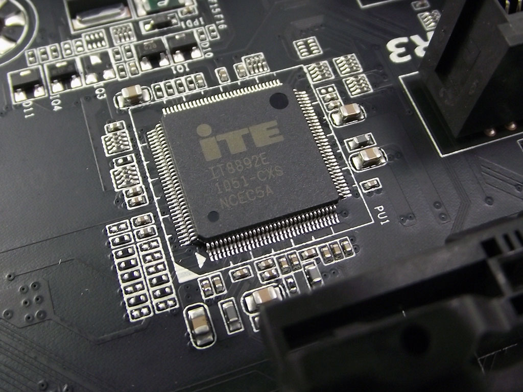
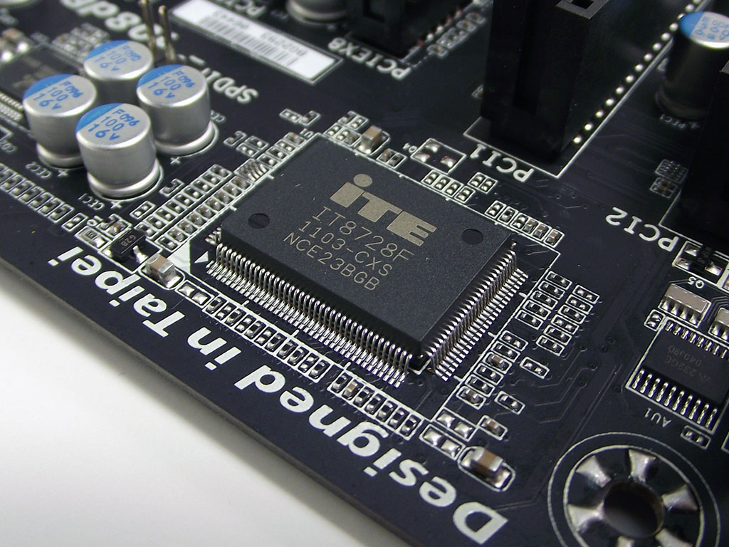
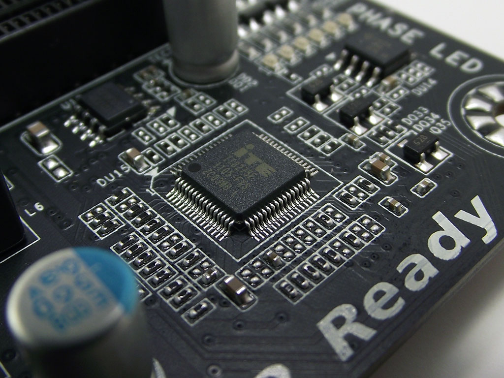
The final two critical components, provided by ITE, are the IT8892E PCIe-to-PCI switch, which provides the needed support for the two PCI slots; and the IT8728F Super I/O, a newer part which provides temperature and voltage monitoring as well as CPU fan control. Of course, all of these parts are together controlled by the BIOS software, which we will examine on the next page.
Jul 28th, 2025 21:16 CDT
change timezone
Latest GPU Drivers
New Forum Posts
- Intel CC150 Submission for Forum (1)
- Windows 12 (236)
- Mouse and CPU usage. (3)
- Warning about DOCP (29)
- need 2tb + SATA SSD ASAP!!! needs to be reliable and not entry level crap (4)
- 2022-X58/1366 PIN Motherboards NVME M.2 SSD BIOS MOD Collection (948)
- What antivirus do you use? (37)
- Upgrade from old x58 system (48)
- Kindly help me to complete my new PC build... (19)
- Which Linux flavor? (77)
Popular Reviews
- Herman Miller Logitech G Embody Review - No Pain, No Gain
- Lian Li O11 Dynamic Mini V2 Review
- Upcoming Hardware Launches 2025 (Updated May 2025)
- Noctua NF-A12x25 G2 PWM Fan Review
- VAXEE XE V2 Wireless Review
- AQIRYS Sirius Pro Review
- Sapphire Radeon RX 9060 XT Pulse OC 16 GB Review - An Excellent Choice
- AMD Ryzen 7 9800X3D Review - The Best Gaming Processor
- UPERFECT UMax 24 Review
- NVIDIA GeForce RTX 5050 8 GB Review
TPU on YouTube
Controversial News Posts
- AMD's Upcoming UDNA / RDNA 5 GPU Could Feature 96 CUs and 384-bit Memory Bus (134)
- AMD Radeon RX 9070 XT Gains 9% Performance at 1440p with Latest Driver, Beats RTX 5070 Ti (131)
- NVIDIA GeForce RTX 5080 SUPER Could Feature 24 GB Memory, Increased Power Limits (115)
- Intel "Nova Lake-S" Core Ultra 3, Ultra 5, Ultra 7, and Ultra 9 Core Configurations Surface (109)
- NVIDIA DLSS Transformer Cuts VRAM Usage by 20% (100)
- DDR6 Memory Arrives in 2027 with 8,800-17,600 MT/s Speeds (99)
- AMD Sampling Next-Gen Ryzen Desktop "Medusa Ridge," Sees Incremental IPC Upgrade, New cIOD (97)
- Intel CEO Confirms SMT To Return to Future CPUs (95)