 0
0
In Win Commander III 600 W Review
Voltage Regulation, Hold-up Time & Inrush Current »A Look Inside & Component Analysis
Before reading this page, we strongly suggest a look at this article, which will help you understand the internal components of a PSU better.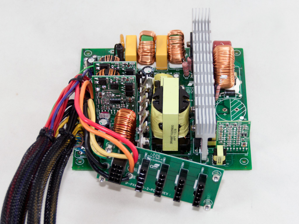


The manufacturer of the PSU is In Win: one of the few unofficial OEM companies that has the know-how and the facilities to build their own PSUs. The PCB is rather small and is not densely populated. It features a clean design without any exotic characteristics, like an LLC converter or a full bridge topology for high efficiency. Nevertheless, DC-DC converters are used with synchronous rectification for the generation of +12V on the secondary side.
The transient filter starts right at the AC receptacle with two Y caps. The power cables are wrapped around a ferrite bead to reduce EMI. On the main PCB, the transient filter continues with two CM chokes, an MOV, two X caps, and a pair of Y caps after the bridge rectifiers.

Two parallel bridge rectifiers are used, and both are bolted onto the primary heatsink.


In the APFC, two STW26NM60N separate the intermediate DC voltage coming from the bridge rectifiers into constant pulse sequences. As boost diode, a BYC10-600 is used. The two parallel hold-up caps are provided by Rubycon (180μF each or 360μF, 450V, 105C). Their combined capacity looks small for the maximum power this unit can deliver, something we will figure out for ourselves during the hold-up-time test.


Two STW26NM60N are used as primary choppers. The combo PFC/PWM controller is a Champion CM6802AHX IC. It is an upgraded version of the widely used CM6800 IC mostly found in Bronze and Silver efficiency PSUs. In Win managed to achieve high efficiency without the use of an LLC converter or a full-bridge topology, which is not as easy as it sounds.

The standby PWM controller is an STR-A6069H IC. The SBR diode that rectifies 5VSB is an STMicroelectronics STPS2045CT.

Synchronous rectification is utilized on the secondary side, and four IPP032N06N3 G fets, installed on a small heatsink, generate the +12V rail. Each one can handle up to 120 A of current, even at 100°C.


The minor rails are generated by two DC-DC converters. Two pairs of G853NL and G603NL fets and an APW7166 PWM controller are used on each DC-DC converter.


On the secondary side, several electrolytic Teapo caps, rated at 105°C, and four polymer caps (also provided by Teapo) are used for filtering purposes. As you will find out later, more should have been used for better ripple suppression.

Housekeeping duties are handled by a Weltrend WT7579 IC for which no information is available on the web.


Soldering quality is quite good on the modular PCB, but, unfortunately, no filtering caps are installed to provide extra ripple filtering. Two thick cables deliver two +12V rails to this PCB. The first feeds the modular 8-pin socket, while the other one powers the four peripheral sockets.

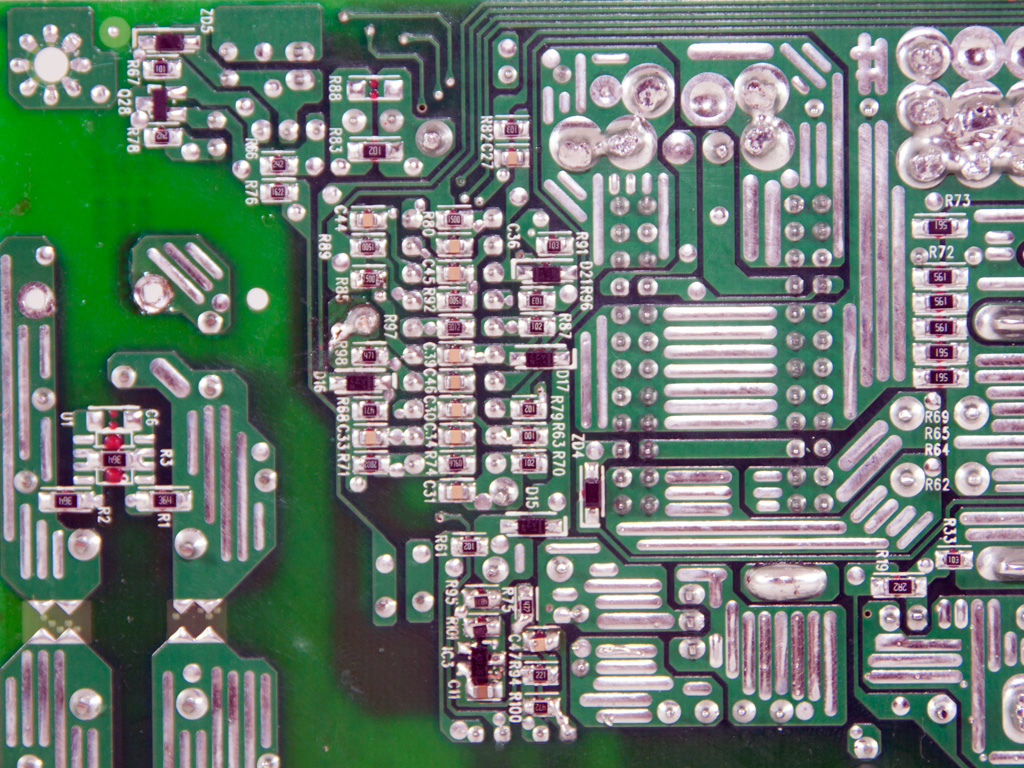
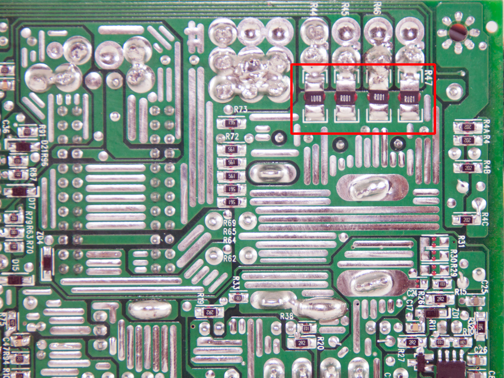


Soldering quality on the main PCB is of very high quality. We usually see such high-quality soldering from large OEMs that dominate the field, and such quality from In Win has amazed us. The four current sense shunts on the secondary side indicate that the PSU does have four +12V virtual rails.

The fan is provided by ADDA, and its model number is ADN512LB-A90 (12V, 0.22A). It uses ball-bearings and is a medium-speed fan, but it does produce a lot of noise at full RPM.
Apr 25th, 2024 11:25 EDT
change timezone
Latest GPU Drivers
New Forum Posts
- Folding Pie and Milestones!! (9007)
- Making Audio Enhancers Work on Windows (2649)
- Random blue screen from winload.efi error (0xc000000e) (1)
- which new soundcard or which 4.1 speakers kits ? (10)
- Alphacool CORE 1 CPU block - bulging with danger of splitting? (8)
- Free Games Thread (3767)
- Only EDP Other in Core? (0)
- RTX 4070 vs RTX 4070 Ti power scaling (7)
- Meta Horizon OS (19)
- Rare GPUs / Unreleased GPUs (1876)
Popular Reviews
- Fractal Design Terra Review
- Thermalright Phantom Spirit 120 EVO Review
- Corsair 2000D Airflow Review
- Minisforum EliteMini UM780 XTX (AMD Ryzen 7 7840HS) Review
- ASUS GeForce RTX 4090 STRIX OC Review
- NVIDIA GeForce RTX 4090 Founders Edition Review - Impressive Performance
- ASUS GeForce RTX 4090 Matrix Platinum Review - The RTX 4090 Ti
- MSI GeForce RTX 4090 Suprim X Review
- MSI GeForce RTX 4090 Gaming X Trio Review
- Gigabyte GeForce RTX 4090 Gaming OC Review
Controversial News Posts
- Sony PlayStation 5 Pro Specifications Confirmed, Console Arrives Before Holidays (116)
- NVIDIA Points Intel Raptor Lake CPU Users to Get Help from Intel Amid System Instability Issues (106)
- AMD "Strix Halo" Zen 5 Mobile Processor Pictured: Chiplet-based, Uses 256-bit LPDDR5X (101)
- US Government Wants Nuclear Plants to Offload AI Data Center Expansion (98)
- Windows 11 Now Officially Adware as Microsoft Embeds Ads in the Start Menu (90)
- Developers of Outpost Infinity Siege Recommend Underclocking i9-13900K and i9-14900K for Stability on Machines with RTX 4090 (85)
- Windows 10 Security Updates to Cost $61 After 2025, $427 by 2028 (84)
- AMD's RDNA 4 GPUs Could Stick with 18 Gbps GDDR6 Memory (83)