 0
0
In Win Glacier 900 W Review
Voltage Regulation & Efficiency »A Look Inside
Before reading this page we strongly suggest to take a look at this article, which will help you understand the internal components of a PSU much better.


The OEM of the PSU is ATNG (thanks to the Jonnyguru forum members Hondacity and Tator Tot for identifying the OEM for me), a manufacturer which we rarely have the opportunity to encounter. Also we should note here that at the time of the review the unit was not listed at the official 80 PLUS site (update: as of 27 September 2011 the PSU is listed on the 80 PLUS site), something that will be done very soon according to In Win.
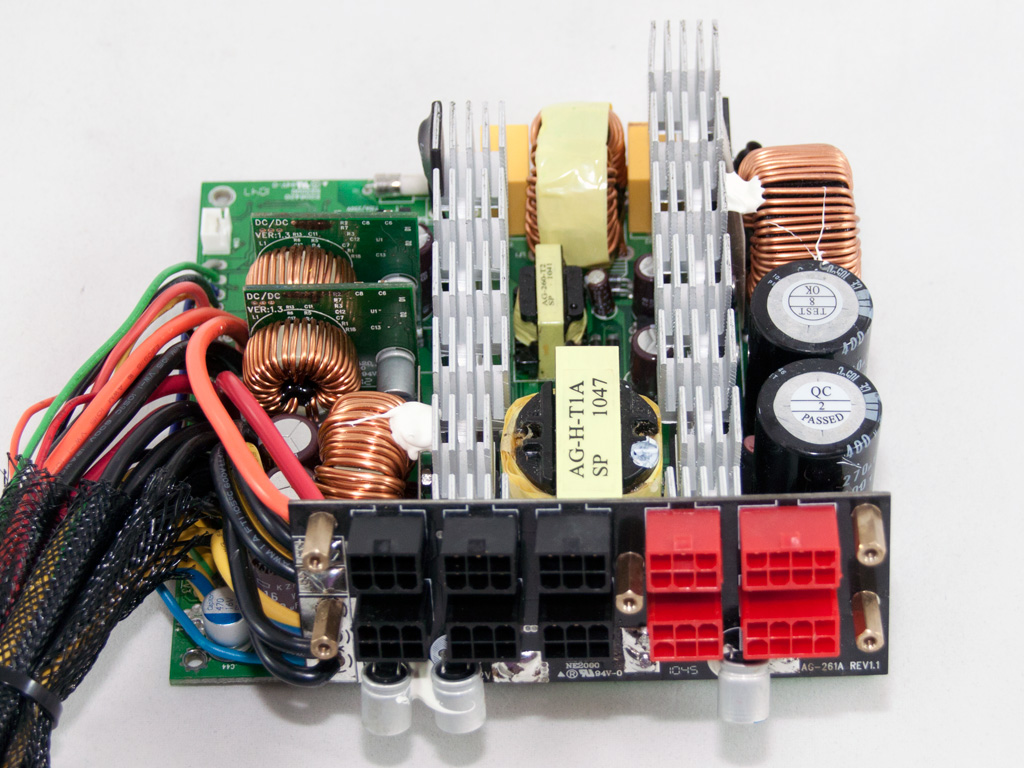
Right behind the AC receptacle there is a small PCB with quite many transient filter components. Namely one CM choke, two X and four X caps. On the main PCB we also found one more CM Choke, two X caps and one more pair of Y caps. Strangely enough the MOV is soldered a little further, after the rectify bridges. As you can see, the transient filtering stage has way more, than the necessary components something that is very good of course.

The bridge rectifiers are bolted together to a dedicated heatsink. Right in front of them resides the MOV along with the PFC input capacitor and two Y caps.


The APFC uses two SPW32N50C3 mosfets and a CREE C3D10060 boost diode. As hold up caps two parallel Nichicon (400V, 270μF each or 540μF total, 105°C) are used. As the DC bus voltage of the APFC is 380V we would like to see at least 420V caps here, but since there is a price difference between 400V and 420/450V caps, many manufacturers choose to use the cheaper ones. Finally, between the primary heatsink and the hold up caps we noticed a resistor which most likely is used for inrush current protection. This has a negative effect on efficiency since thermistors once heated lower their resistance thus energy losses are decreased, something that is not the case with resistors that keep almost the same resistance at all cases. In a Gold PSU we expected to find a thermistor along with a bypass relay but as it seems the manufacturer was pretty confident about the efficiency this platform can deliver.


The PFC controller (PCSM 3845B) is soldered on a vertical daughter-board in the primary side while what looks to be the PWM controller resides on the solder side of the main PCB. Unfortunately we couldn't identify the latter since all markings on it were erased and the markings on the first were partially erased too, so we had a very hard time reading them. The primary switches are two SPW24N60C3.

Near the primary heatsink the standby PWM controller is soldered, a TNY277 IC.


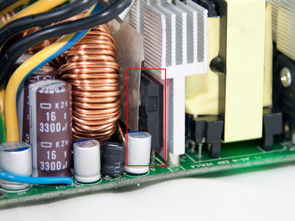

In the secondary side semi-synchronous (SR) design is used so for the generation of +12V both SBRs (Schottky Barrier Diodes) and mosfets are used. More specific four IPP028N08N3 FETs and two PFR60L60PT are used. Two DC-DC converters which are fed from +12V handle the generation of the minor rails. In each there is one CAT7523 PWM controller and four ME90N03 FETs.

In the secondary side most of the filtering capacitors are polymer ones and provided by CapXon. We also find some electrolytics (Nippon Chemi-Con) which are rated at 105°C. The thermistor responsible for the fan's RPM control resides of course on the secondary heatsink.

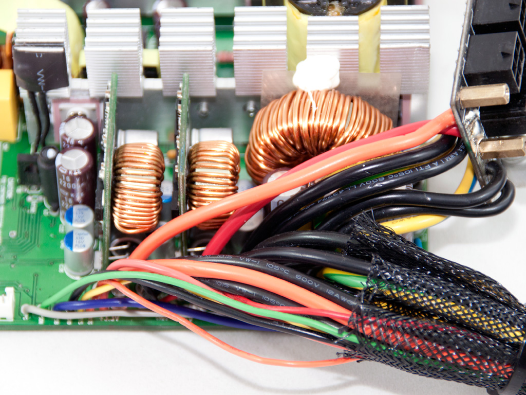
On the front of the modular PCB three polymer caps further reduce AC ripple. Also notice the thick 12AWG wires that transfer voltages along with ground to the modular PCB. The thicker the wires the lower the resistance thus voltage drops are much lower as the current increases.
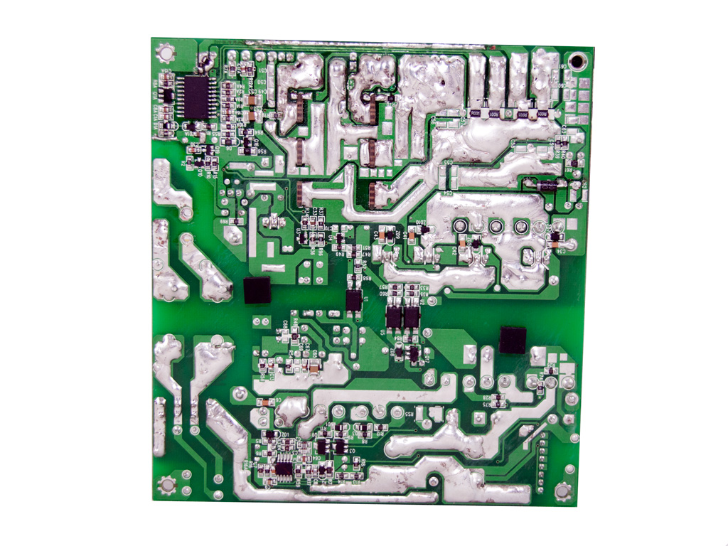
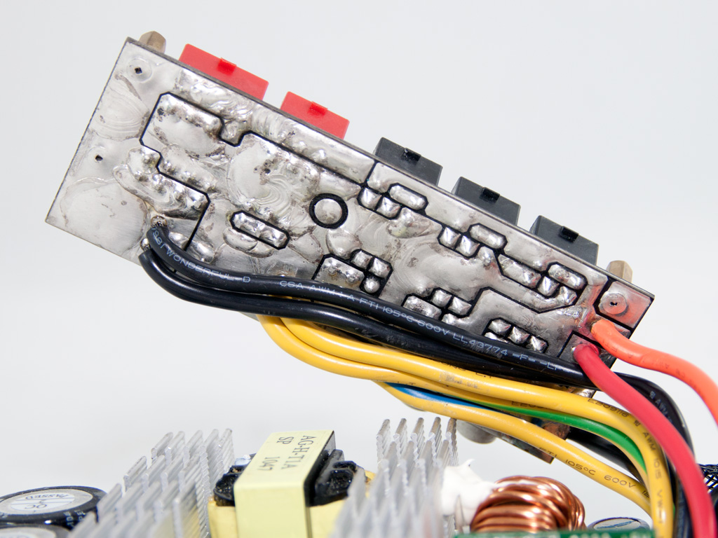
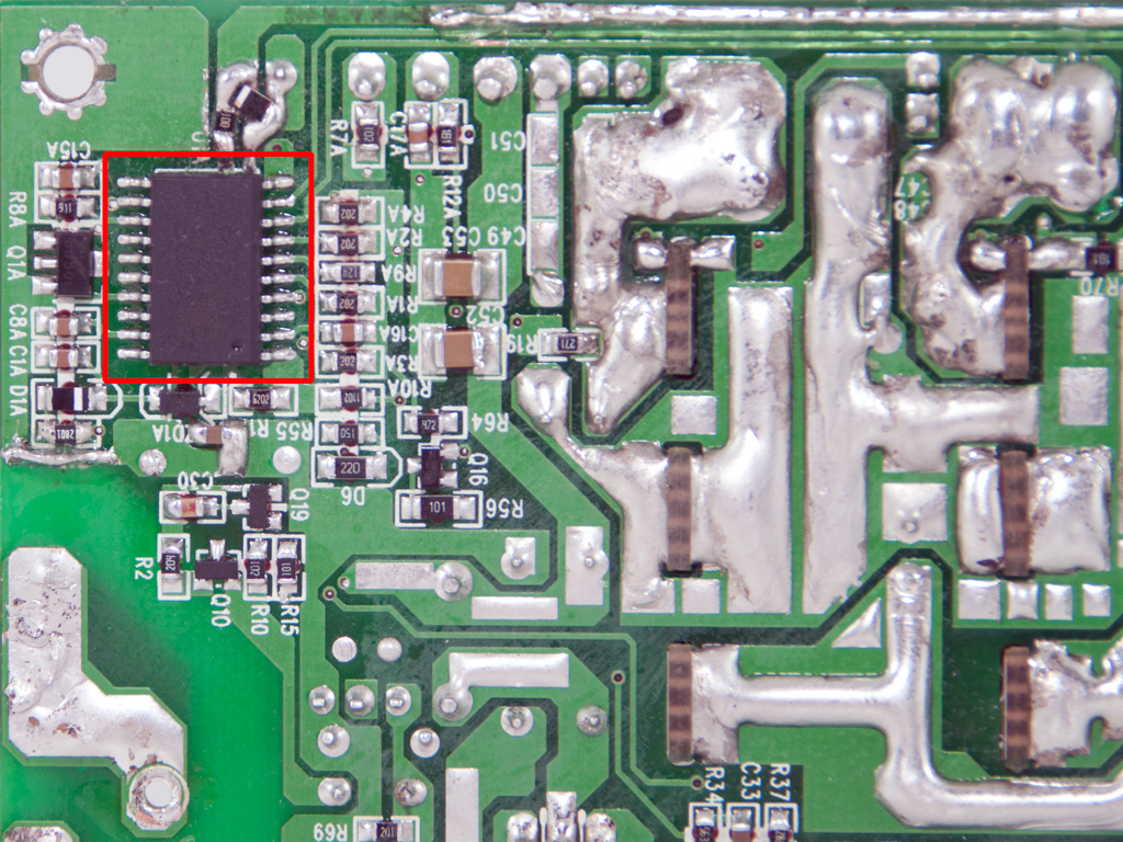

Apparently our unit was one of the first samples so soldering quality is pretty low. We spotted many hand made solder joints with excess amount of solder used on both the main and the modular PCBs. On the solder side of the main PCB we also found the protections IC, a PS232S and in the area where +12V leaves the PCB, we spotted four shunt resistors so this platform supports up to four +12V rails (the PS232S supports four +12V channels too).

The cooling fan is provided by Globe Fan and its model number is RL4Z B1352512H (12V, 0.33A, 106.86CFM, 1500RPM, 29.2dBA). A triangular plastic baffle is attached to the fan to direct airflow towards the front side of the PSU.
Apr 26th, 2024 23:00 EDT
change timezone
Latest GPU Drivers
New Forum Posts
- Black screens leading to restarts (Event ID 18) on AMD platform since changing graphics card (43)
- FINAL FANTASY XIV: Dawntrail Official Benchmark (73)
- Your PC ATM (34509)
- Rare GPUs / Unreleased GPUs (1877)
- looking to build a new system and im considering asrock brand but i have some doubts/concerns. (15)
- AAF Optimus DCH Audio Modded Driver for Windows 10/11 - For ALL HDAUDIO Enumerator Chips (652)
- Help me identify rx 580 card ? (0)
- Strange system crashes out of nowhere help (9)
- What phone you use as your daily driver? And, a discussion of them. (1494)
- Secure boot already open help (11)
Popular Reviews
- Ugreen NASync DXP4800 Plus Review
- HYTE THICC Q60 240 mm AIO Review
- Quick Look: MOONDROP CHU 2 Budget In-Ear Monitors
- MOONDROP x Crinacle DUSK In-Ear Monitors Review - The Last 5%
- Thermalright Phantom Spirit 120 EVO Review
- Upcoming Hardware Launches 2023 (Updated Feb 2024)
- Alienware Pro Wireless Gaming Keyboard Review
- CeBIT 2008: Akasa Review
- FiiO K19 Desktop DAC/Headphone Amplifier Review
- CeBIT 2008: Cyber E Sport Review
Controversial News Posts
- Windows 11 Now Officially Adware as Microsoft Embeds Ads in the Start Menu (135)
- Sony PlayStation 5 Pro Specifications Confirmed, Console Arrives Before Holidays (117)
- NVIDIA Points Intel Raptor Lake CPU Users to Get Help from Intel Amid System Instability Issues (106)
- AMD "Strix Halo" Zen 5 Mobile Processor Pictured: Chiplet-based, Uses 256-bit LPDDR5X (103)
- US Government Wants Nuclear Plants to Offload AI Data Center Expansion (98)
- AMD's RDNA 4 GPUs Could Stick with 18 Gbps GDDR6 Memory (95)
- Developers of Outpost Infinity Siege Recommend Underclocking i9-13900K and i9-14900K for Stability on Machines with RTX 4090 (85)
- Windows 10 Security Updates to Cost $61 After 2025, $427 by 2028 (84)