 0
0
Thermaltake SMART 730 W Review
Ripple Measurements »Advanced Transient Response Tests
In these tests we monitor the response of the PSU in two different scenarios. First a transient load (11A at +12V, 5A at 5V, 6A at 3.3V and 0.5A at 5VSB) is applied for 50 ms to the PSU, while the latter is working at a 20% load state. In the second scenario the PSU, while working with 50% load, is hit by the same transient load. In both tests, we measure the voltage drops that the transient load causes, using our oscilloscope. In any case voltages should remain within the regulation limits specified by the ATX specification. We must stress here, that the above tests are crucial, since they simulate transient loads that a PSU is very likely to handle (e.g. starting of a RAID array, an instant 100% load of CPU/VGAs etc.) We call these tests “Advanced Transient Response Tests” and they are designed to be very tough to master, especially for PSUs with capacities lower than 500W.| Advanced Transient Response 20% | ||||
|---|---|---|---|---|
| Voltage | Before | After | Change | Pass/Fail |
| 12 V | 11.954V | 11.779V | 1.46% | Pass |
| 5 V | 4.993V | 4.852V | 2.82% | Pass |
| 3.3 V | 3.299V | 3.151V | 4.49% | Pass |
| 5VSB | 4.922V | 4.831V | 1.83% | Pass |
| Advanced Transient Response 50% | ||||
|---|---|---|---|---|
| Voltage | Before | After | Change | Pass/Fail |
| 12 V | 11.850V | 11.698V | 1.28% | Pass |
| 5 V | 4.924V | 4.775V | 3.03% | Pass |
| 3.3 V | 3.216V | 3.063V | 4.76% | Fail |
| 5VSB | 4.859V | 4.769V | 1.85% | Pass |
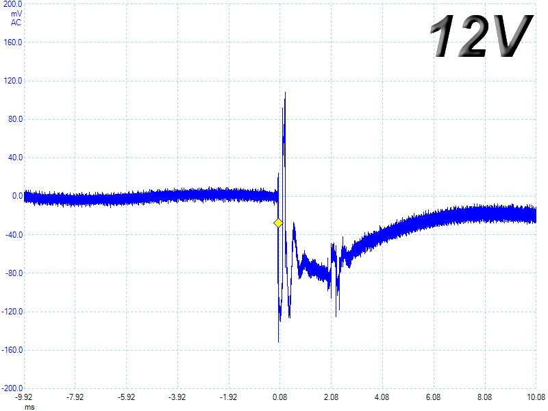
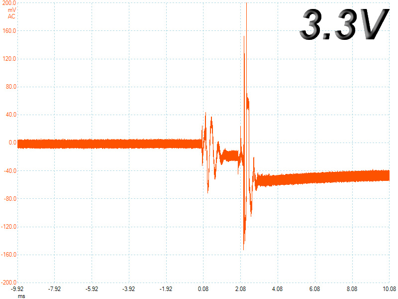
On the +12V rail the registered voltage drops are well controlled so voltage readings on this rail are constantly away from the lower limit. At 5V and 5VSB the deviations are larger but still within limits. The weak chain here is the 3.3V rail which although it doesn't register a deviation above 5% thanks to its already low voltage, because of the loose voltage regulation, in the second test its voltage reading is way below the corresponding limit.
Below you will find the oscilloscope screenshots that we took during Advanced Transient Response Testing.
Transient Response at 20% Load
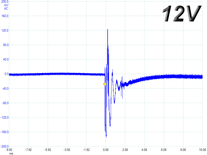
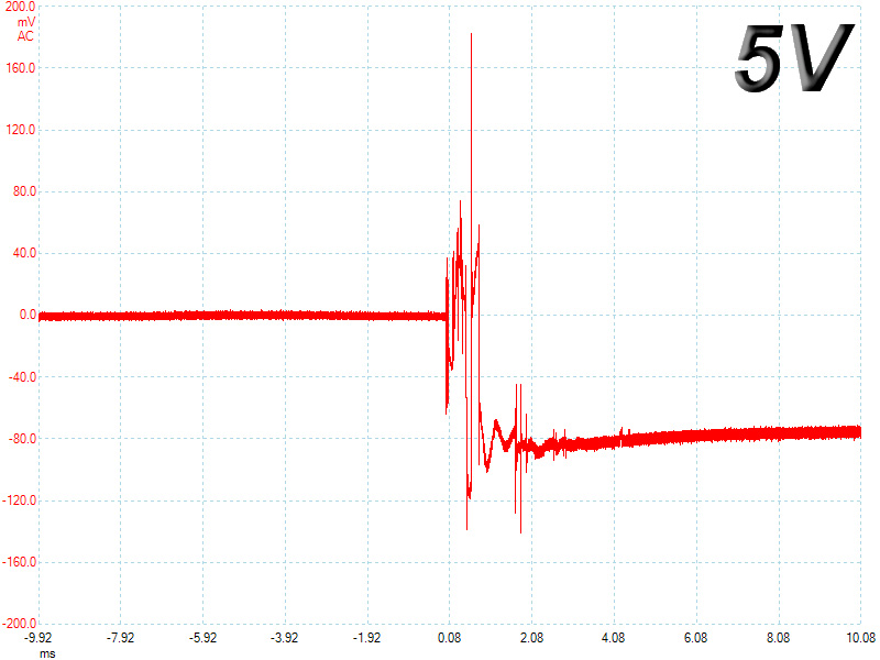
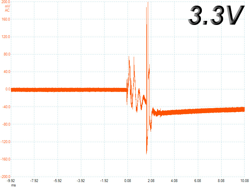

Transient Response at 50% Load


Turn-On Transient Tests
In the next set of tests we measure the response of the PSU in simpler scenarios of transient loads, during the turn on phase of the PSU. In the first test we turn off the PSU, dial 2A load at 5VSB and then switch on the PSU. In the second test, while the PSU is in standby, we dial the maximum load that +12V can handle and we start the PSU. In the last test, while the PSU is completely switched off (we cut off power or switch off the PSU's On/Off switch), we dial the maximum load that +12V can handle and then we switch on the PSU from the loader and we restore power. The ATX specification states that recorded spikes on all rails should not exceed 10% of their nominal values (e.g. +10% for 12V is 13.2V and for 5V is 5.5V).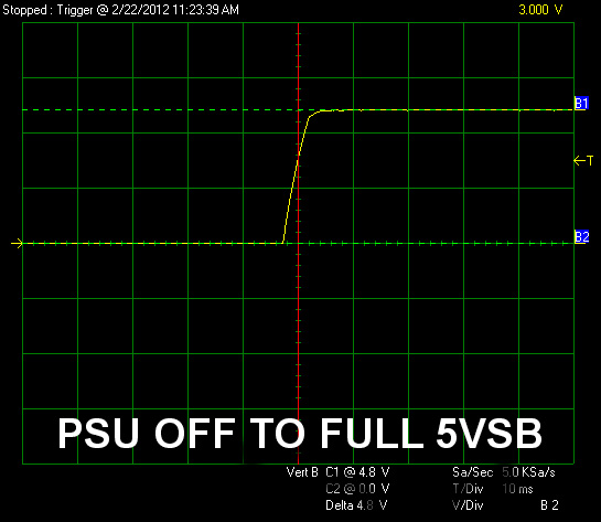


At 5VSB there are no voltage overshoots and the waveform is good. On the +12V rail, in both tests, we didn't notice any serious spikes but the waveforms are not ideal since in the first test (standby to full 12V) the voltage takes quite some time to settle down while in the second test (PSU off to full 12V) the waveform does not ramp up smoothly. Nevertheless, despite the non perfect waveforms during both +12V tests, the most important here is that there are no voltage overshoots, at least above the nominal voltage, so the results are definitely in spec.
Apr 28th, 2024 15:13 EDT
change timezone
Latest GPU Drivers
New Forum Posts
- Ryzen Owners Zen Garden (7260)
- How Are My RAM Consumption Values? (2)
- Overclocking A8 6500 CPU (7)
- Realtek Modded Audio Driver for Windows 10/11 - Only for HDAUDIO (5691)
- Ghetto Mods (4323)
- Vintage hardware question! (14)
- Share your AIDA 64 cache and memory benchmark here (2919)
- DTS DCH Driver for Realtek HDA [DTS:X APO4 + DTS Interactive] (1910)
- What's your latest tech purchase? (20356)
- Anyone know if Rufus gets around the SSE4.2 issue with Windows 11 24H2? (39)
Popular Reviews
- Ugreen NASync DXP4800 Plus Review
- HYTE THICC Q60 240 mm AIO Review
- Upcoming Hardware Launches 2023 (Updated Feb 2024)
- MOONDROP x Crinacle DUSK In-Ear Monitors Review - The Last 5%
- Thermalright Phantom Spirit 120 EVO Review
- AMD Ryzen 7 7800X3D Review - The Best Gaming CPU
- FiiO K19 Desktop DAC/Headphone Amplifier Review
- ASUS Radeon RX 7900 GRE TUF OC Review
- MSI GeForce RTX 4060 Ventus 2X OC Review
- Alienware Pro Wireless Gaming Keyboard Review
Controversial News Posts
- Windows 11 Now Officially Adware as Microsoft Embeds Ads in the Start Menu (139)
- Sony PlayStation 5 Pro Specifications Confirmed, Console Arrives Before Holidays (117)
- NVIDIA Points Intel Raptor Lake CPU Users to Get Help from Intel Amid System Instability Issues (106)
- AMD "Strix Halo" Zen 5 Mobile Processor Pictured: Chiplet-based, Uses 256-bit LPDDR5X (103)
- US Government Wants Nuclear Plants to Offload AI Data Center Expansion (98)
- AMD's RDNA 4 GPUs Could Stick with 18 Gbps GDDR6 Memory (95)
- Developers of Outpost Infinity Siege Recommend Underclocking i9-13900K and i9-14900K for Stability on Machines with RTX 4090 (85)
- Windows 10 Security Updates to Cost $61 After 2025, $427 by 2028 (84)