 0
0
Thermaltake Toughpower XT Platinum 1275 W Review
Voltage Regulation & Efficiency »A Look Inside
Before reading this page we strongly suggest to take a look at this article, which will help you understand the internal components of a PSU much better.


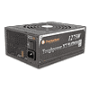
The OEM of the unit is easily recognizable by the green transformers. For those that didn't figure it out yet, it's Channel Well Technology or CWT, a major PSU manufacturer with lots of experience in this area. The platform used in this PSU incorporates the best solutions today's technology has to offer, to achieve the best possible performance. This high-end technology and the quality components used are the main reasons for the stiff price. In order to provide you a better view we removed the APFC and primary heatsinks.
The first part of the transient filtering stage starts right at the AC receptacle with one X and two Y caps. On the main PCB we find the rest transient filtering componets, namely two pairs of X and Y caps, two CM chokes and an MOV. Overall the transient filter is complete.

There are three parallel bridge rectifiers which are bolted on heatsinks. Their model number is GBU1006 so in total they can handle up to 30A! This is a crazy high current but the main reason behind the utilization of three bridges is not to handle such an amount of power, but to increase efficiency.


Next we meet the interleaved PFC circuit. To make it easier to follow for the less experienced, in PSU's design, readers the word "interleaved" means that actually there are two APFC converters which work in parallel with a phase difference among them. This leads into minimized input/output current ripple, lower conduction losses - higher efficiency and doubling of the effective switching frequency. Each APFC converter uses an IPW60R099CP mosfet and a CREE CSD10060 boost diode. Next to each boost diode there is a current sense inductor (wrapped in heat-shrink tubing), one for each APFC converter. The hold up caps are two Nippon Chemi-Con (400V, 560µF, 105°C, KMQ series).
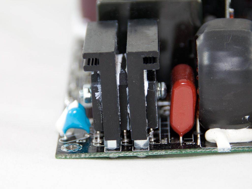
The Interleaving Continuous Conduction Mode PFC controller is a UCC28070. It is soldered on a vertical PCB and normally totally hidden by the primary heatsink, which is absent in the photo above.

Between the resonant tank and one of the transformers used by the APFC circuit there is a small electromagnetic relay and the thermistor responsible for inrush protection.

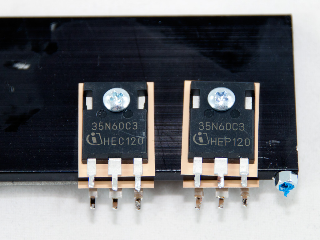
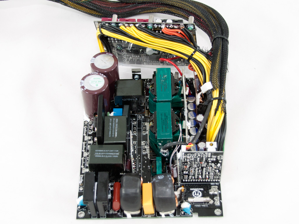
In order to minimize switching losses, and thus increase efficiency, along with the LLC resonant converter a full bridge topology is used so as primary switches four SPW35N60C3 mosfets are present.

There are two parallel main transformers and on one of them resides the thermistor which is responsible for fan speed control. In the sample we had in our hands we suspected that the thermistor didn't make good contact, since the fan started only at very high ambient, so we removed it, applied some thermal paste and re-install it. Afterwards the fan started spinning at lower and safer temperatures. In our opinion this thermistor should be bolted to a heatsink and not simply glued onto the transformer. We hope that CWT will fix this issue because the late fan's startup leads to increased stress on all PSU components and greatly reduces their lifespan.


In the secondary side synchronous design is used of course and on two vertical PCBs all mosfets responsible for the +12V rails regulation are soldered. Every PCB holds six IPD031N06L mosfets so in total we have twelve mosfets for the +12V rail! In the secondary, mostly polymer caps are used for filtering purposes, something that we rarely see even in high-end PSUs. The few electrolytic caps used in the secondary side are provided by Chemi-Con.

The protections IC, a PS229, is soldered on a vertical PCB in the secondary side. Strangely enough it supports only one +12V OCP channel so the OCP protection for the second +12V virtual rail should be implemented via another solution.


The VRMs that generate the minor rails are located on the modular PCB. A technique already utilized by Enermax and Seasonic in order to minimize power losses on these two rails. In total four M3004D and four M3006D mosfets rectify the 3.3V and 5V rails respectively. The common PWM controller is an APW7159. In front of the modular PCB several polymer caps along with two inductors are used for the filtering and rectification of the two afore-mentioned rails. Although the purpose of putting the VRMs, which are responsible for the minor rails generation, directly onto the modular PCB is to minimize energy losses by avoiding the use of wires to transfer these rails. In this case lots of small wires are used to transfer the 3.3V rail to the top side of the modular PCB. Apparently there wasn't any space to make a PCB trace and lead 3.3V there so wires had to be used, so the advantage of having the 3.3V VRM on the modular PCB is partially lost.


On the front of the modular PCB we find several small polymer caps that further reduce ripple on the DC outputs.
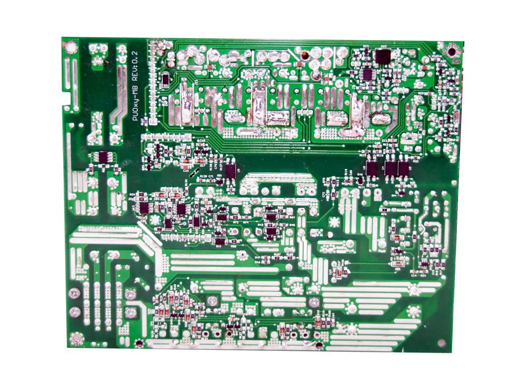


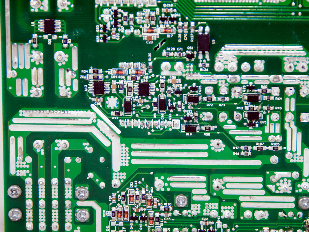
Soldering quality is fairly good and thankfully we didn't spot any long component leads, which we hate to see since they can cause much trouble (shorts).

The cooling fan has Thermaltake's logo on it and its model number is TT-1425B (12V, 0.7A). With a little search on the Internet we found that this fan is actually a rebadged Yate Loon D14BM-12 (12V, 1400 RPM, 62.0 CFM, 29dBA). Thanks to its low max RPMs it doesn't produce much noise and because of the unit's Platinum efficiency its control circuit will keep a low fan speed most of the time.
Apr 25th, 2024 04:45 EDT
change timezone
Latest GPU Drivers
New Forum Posts
- Core i5-6300U (14)
- (Anti) SFF fun house (351)
- Alphacool CORE 1 CPU block - bulging with danger of splitting? (4)
- The TPU UK Clubhouse (24786)
- Github comments used to push malware via Microsoft repo urls (3)
- Bizarre Throttlestop issue (5)
- GTX 1070 Ti - TDP Issues - Always Power Throttling (5)
- What phone you use as your daily driver? And, a discussion of them. (1471)
- What's your latest tech purchase? (20337)
- The Official Linux/Unix Desktop Screenshots Megathread (694)
Popular Reviews
- Fractal Design Terra Review
- Thermalright Phantom Spirit 120 EVO Review
- Corsair 2000D Airflow Review
- Minisforum EliteMini UM780 XTX (AMD Ryzen 7 7840HS) Review
- ASUS GeForce RTX 4090 STRIX OC Review
- NVIDIA GeForce RTX 4090 Founders Edition Review - Impressive Performance
- ASUS GeForce RTX 4090 Matrix Platinum Review - The RTX 4090 Ti
- MSI GeForce RTX 4090 Suprim X Review
- MSI GeForce RTX 4090 Gaming X Trio Review
- Gigabyte GeForce RTX 4090 Gaming OC Review
Controversial News Posts
- Sony PlayStation 5 Pro Specifications Confirmed, Console Arrives Before Holidays (116)
- NVIDIA Points Intel Raptor Lake CPU Users to Get Help from Intel Amid System Instability Issues (106)
- AMD "Strix Halo" Zen 5 Mobile Processor Pictured: Chiplet-based, Uses 256-bit LPDDR5X (101)
- US Government Wants Nuclear Plants to Offload AI Data Center Expansion (98)
- Windows 10 Security Updates to Cost $61 After 2025, $427 by 2028 (84)
- Developers of Outpost Infinity Siege Recommend Underclocking i9-13900K and i9-14900K for Stability on Machines with RTX 4090 (84)
- Windows 11 Now Officially Adware as Microsoft Embeds Ads in the Start Menu (79)
- TechPowerUp Hiring: Reviewers Wanted for Motherboards, Laptops, Gaming Handhelds and Prebuilt Desktops (78)