 9
9
Origen AE S21T HTPC Enclosure Review
Installation »Case Insides
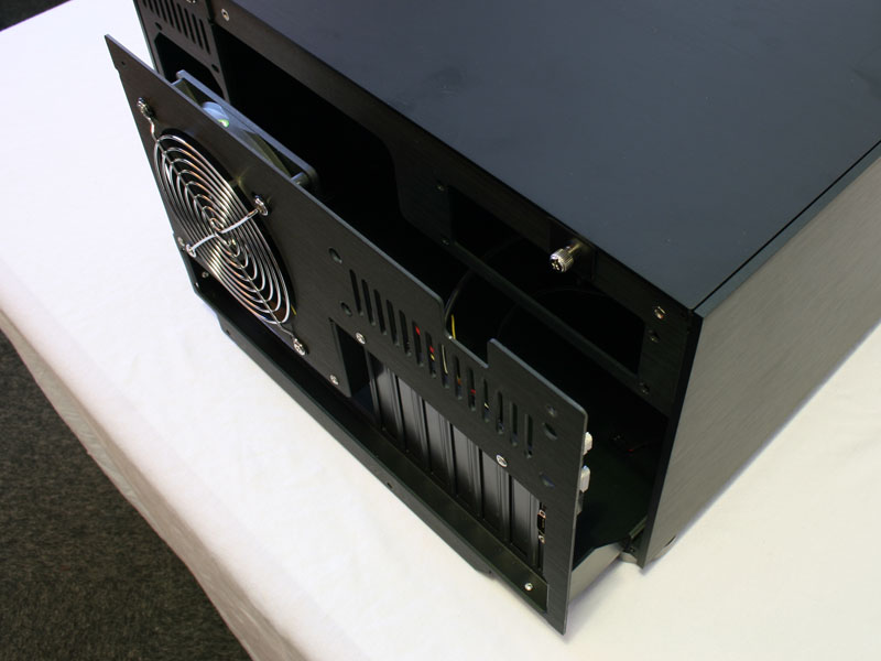

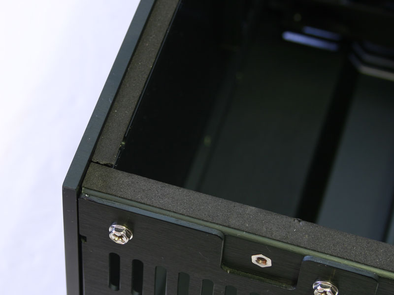
The mainboard tray is removable, even when the rest of the system is closed. You simply remove four thumb screws and can then pull the tray out of the chassis. Opening the top of the S21T is done by removing two additional thumb screws. Origen AE has kept the entire case in black, even the inside. The inner layout is just as you would expect, with the single optical drive in the center and the hard drive bays on either side, toward the front. This is the same general layout as the Moneual LAB case we reviewed here, but much more elaborate. There are thin foam spacers to reduce vibrations when the case is closed. These small details make the difference!


The mainboard tray does not bare any real surpises and the appropriate standoffs come pre-installed. As you can see, the case can hold a MicroATX or full size ATX mainboard. One of the PCI brackets is filled with a small PCB and an external VGA connector. Origen AE has designed this PCB specifically for the enclosure, instead of simply routing the display signal through a thick cable to the back of the S21T.

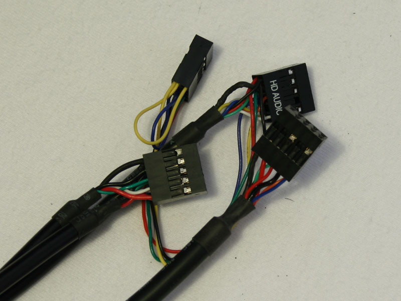
The connectors used for this purpose are thin, just as the attached cables. This should make it easier to route them nicely and you have complete choice where to place the PCI slot with the VGA connector. While this may be unique, the mainboard headers are of the usual kind and the audio connector is available in HD audio or AC'97. There is no third, all seperated plug in case you have an older board. This is another subtle hint, telling you to better install some high end components inside this enclosure.

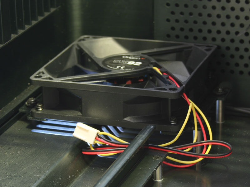
The hard drive bay consists of two bars and heatsink like grooves, while the fan used for cooling is of the 92 mm kind with a mainboard header. Origen AE opted for such connectivity for all fans inside the S21T, which is perfect. It is interesting to see that 92 mm fans are used instead of the smaller 80 mm variety. This choice of fans will cause problems later on in this review.


The optical drive bay cover needs to be removed to install a DVD, or preferably BluRay or HD-DVD drive. This is done by unscrewing four screws, two on either side.

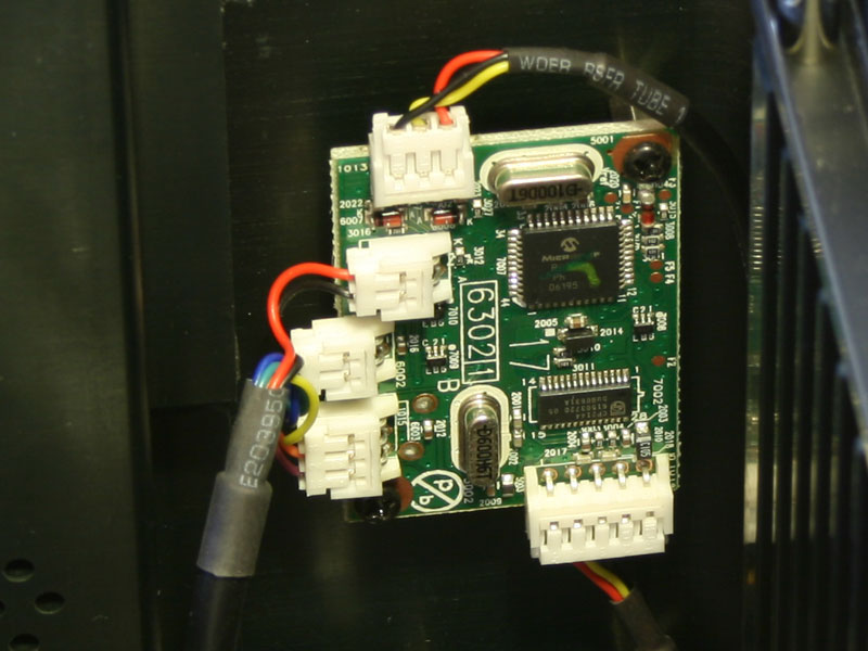

You will find three colors of PCBs inside the case. The electrical motor, which drives the display up and down utilizes blue PCB, while there is a small green PCB responsible for the LCD and the touch screen functionality. Note the sheer amount of cables already connected and routed nicely.
The third color, yellow, is found in form of the front I/O PCB which also holds the card reader. Another interesting aspect is the fact that this PCB utilizes a single USB 2.0 header, so you do not loose any connectivity due to the card reader. Other cases require you to plug in the card reader seperately instead of combining everything into a single USB 2.0 header. This means you plug the cable into the mainboard, then you are able to use the card reader and have two USB 2.0 plugs in the front of the case - one mainboard header used, two USB 2.0 connections gained, simply perfect.
May 21st, 2024 05:05 EDT
change timezone
Latest GPU Drivers
New Forum Posts
- Why I love Gaming (10)
- What's your latest tech purchase? (20605)
- Xonotic the-big-keybench demo results (4)
- Ryzen 5 5600x stock overclocked reaching high temps (0)
- Asus 7 PIN fans to standard 4 pin PWM? (13)
- TPU's Nostalgic Hardware Club (18521)
- MSI Z370 SLI PLUS + i9 9900k bad perfomance. (28)
- What are you playing? (20718)
- For general use - moving files around and playing games, would you have an Optane boot drive or PCie gen 5? (60)
- Post your Cinebench 2024 score (462)
Popular Reviews
- Ghost of Tsushima Performance Benchmark Review - 35 GPUs Tested
- Ghost of Tsushima: DLSS vs. FSR vs. XeSS Comparison Review
- PNY XLR8 Gaming EPIC-X RGB DDR5-6400 CL32 32 GB Review
- TerraMaster D8 Hybrid Review
- Silverstone Shark Force 120 mm Fan Review
- Homeworld 3 Performance Benchmark Review - 35 GPUs Tested
- Upcoming Hardware Launches 2023 (Updated Feb 2024)
- Lofree Edge Ultra-Low Profile Wireless Mechanical Keyboard Review
- AMD Ryzen 7 7800X3D Review - The Best Gaming CPU
- AMD Ryzen 7 7700 Review - Affordable Zen 4 Powerhouse
Controversial News Posts
- Intel Statement on Stability Issues: "Motherboard Makers to Blame" (269)
- AMD to Redesign Ray Tracing Hardware on RDNA 4 (227)
- Windows 11 Now Officially Adware as Microsoft Embeds Ads in the Start Menu (173)
- NVIDIA to Only Launch the Flagship GeForce RTX 5090 in 2024, Rest of the Series in 2025 (154)
- AMD Hits Highest-Ever x86 CPU Market Share in Q1 2024 Across Desktop and Server (140)
- AMD RDNA 5 a "Clean Sheet" Graphics Architecture, RDNA 4 Merely Corrects a Bug Over RDNA 3 (139)
- AMD's RDNA 4 GPUs Could Stick with 18 Gbps GDDR6 Memory (114)
- AMD Ryzen 9 7900X3D Now at a Mouth-watering $329 (104)