 1
Akasa Venom Power 850 W Review
Ripple Measurements »Advanced Transient Response Tests
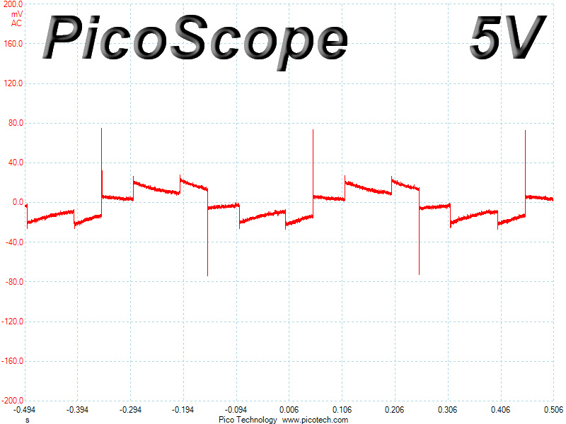
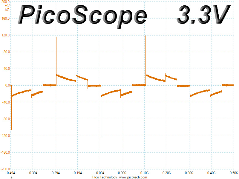
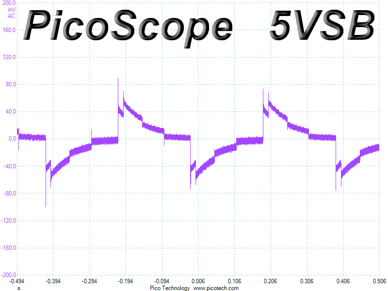
In these tests, we monitor the response of the PSU in two different scenarios. First, a transient load (10 A at +12V, 5 A at 5V, 5 A at 3.3V, and 0.5 A at 5VSB) is applied to the PSU for 200 ms while the latter is working at a 20% load state. In the second scenario, the PSU, while working at 50% load, is hit by the same transient load. In both tests, we measure the voltage drops that the transient load causes using our oscilloscope. The voltages should remain within the regulation limits defined by ATX specification. We must stress here that the above tests are crucial since they simulate transient loads that a PSU is very likely to handle (e.g., booting a RAID array, an instant 100% load of CPU/VGAs, etc.) We call these tests "Advanced Transient Response Tests", and they are designed to be very tough to master, especially for PSUs with capacities lower than 500 W.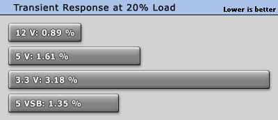
| Advanced Transient Response 20% | ||||
|---|---|---|---|---|
| Voltage | Before | After | Change | Pass/Fail |
| 12 V | 12.107V | 11.999V | 0.89% | Pass |
| 5 V | 5.099V | 5.017V | 1.61% | Pass |
| 3.3 V | 3.401V | 3.293V | 3.18% | Pass |
| 5VSB | 5.052V | 4.984V | 1.35% | Pass |
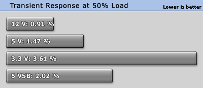
| Advanced Transient Response 50% | ||||
|---|---|---|---|---|
| Voltage | Before | After | Change | Pass/Fail |
| 12 V | 12.036V | 11.927V | 0.91% | Pass |
| 5 V | 5.042V | 4.968V | 1.47% | Pass |
| 3.3 V | 3.348V | 3.227V | 3.61% | Pass |
| 5VSB | 4.958V | 4.858V | 2.02% | Pass |
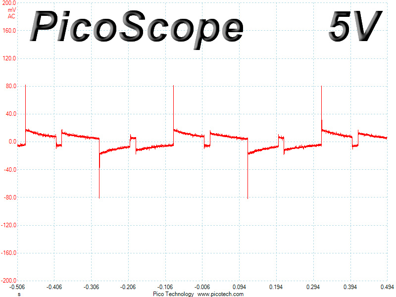
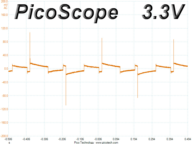
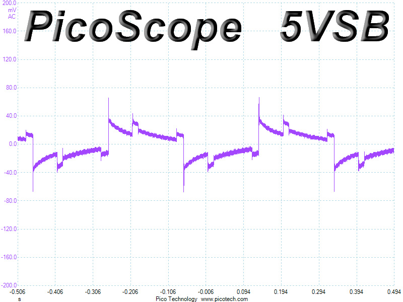
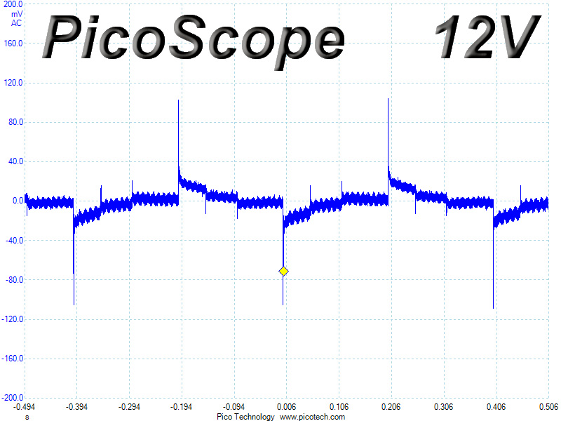
The response of the PSU in dynamic loads is quite good, and voltage drops on all rails were well controlled, especially on the +12V rail which registered a deviation below 1%. The rail that registered the largest deviation was the 3.3V one, but it still managed to keep its voltage well above 3.2V throughout.
Below, you will find the oscilloscope screenshots that we took during Advanced Transient Response Testing.
Transient Response at 20% Load
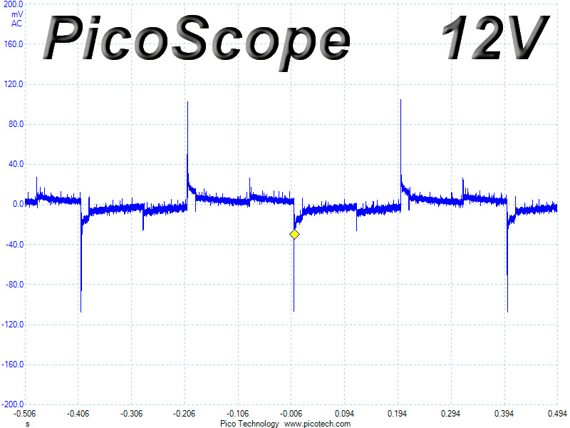
Transient Response at 50% Load
Turn-On Transient Tests
We measure the response of the PSU in simpler scenarios of transient loads - during the power-on phase of the PSU - in the next set of teset. In the first test, we turn the PSU off, dial the maximum current that the 5VSB can output, and then switch on the PSU. In the second test, we dial the maximum load that +12V can handle and we start the PSU while it is in standby mode. In the last test, while the PSU is completely switched off (we cut off power or switch off the PSU's on/off switch), we dial the maximum load that the +12V rail can handle before switching the PSU on from the loader and restoring power. The ATX specification states that recorded spikes on all rails should not exceed 10% of their nominal values (e.g., +10% for 12V is 13.2V and for 5V is 5.5V).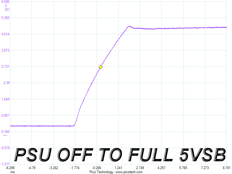
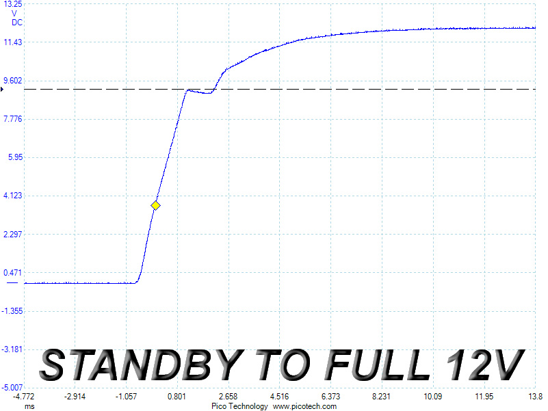
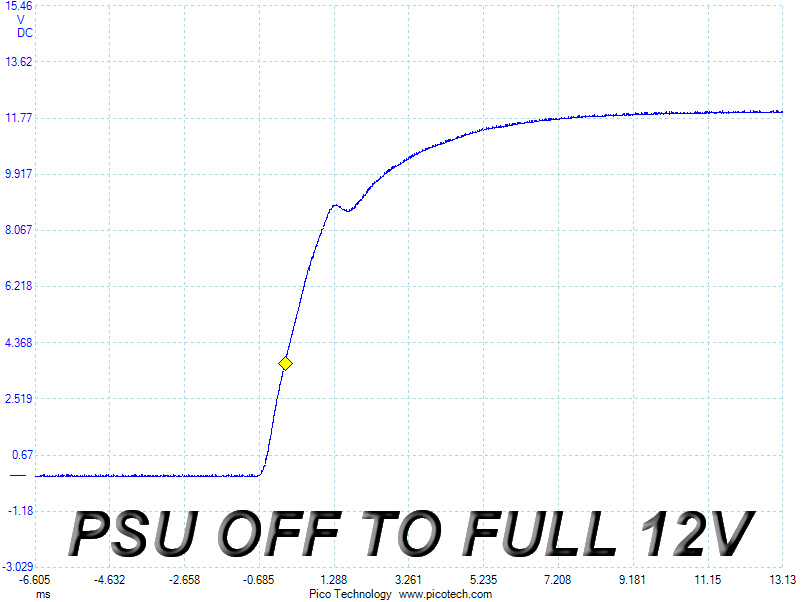
We measured a small spike that passes the nominal voltage by only 0.03V on the 5VSB rail. The voltage overshoot reached up to 12.11V on the +12V rail, which is way lower than the limit that the ATX spec sets. The slope doesn't ramp up smoothly and makes a small step around 9V. It, however, won't cause any problems because it lasts for a very short period of time.
Nov 13th, 2026 23:26 CST
change timezone
Latest GPU Drivers
New Forum Posts
- no "PhysX" workable (9)
- What are you playing? (26215)
- Tell me about your favourite graphics card (32)
- AI generated images... (224)
- Crimson Desert (31)
- RenoDX HDR - how to view the differnce Before&After in game? (0)
- Displayport DP80 3M (10ft) cable that can achieve 80gbps stable? (5)
- I'll flash a ASUS ROG Strix RX480 O8G in Cause of Code 43, as a Newbie (1)
- Opinion on Monitor Replacement (6)
- TMOG - post your benchmark results here (16)
Popular Reviews
- AMD Zen 6 Technical Deep Dive
- Corsair HX1000i Shift Crystal Review
- NZXT C1200 Platinum Review
- Upcoming Hardware Launches 2027 (Updated Nov 2026)
- ASUS ROG Strix B850-I Gaming Wi-Fi7 W Review
- Montech King 95 3D PRO Review
- NZXT H7 RGB+ Review
- NZXT H5 Review
- Phantom Blade Zero Performance Benchmark Review - 35 GPUs Tested
- XPG NIMBUS PLUS Review - Mid-range Chair With Strong Competitors
TPU on YouTube
Controversial News Posts
- NVIDIA Co-Founder and CEO Jensen Huang Officially Resigns (380)
- OpenAI CEO Argues Home PCs Waste the World's Limited DRAM Supply (152)
- NVIDIA Launches Investigation Into Jensen Huang's Relationship With Suspected Chinese Spy (136)
- Intel "Raptor Lake Next" 16-Core and 20-Core CPUs Surface (130)
- Legendary Game Studio BioWare Shuts Down Following EA Layoffs (104)
- Dell CEO Says the Memory Shortage Will Get Worse in 2027 (95)
- NVIDIA GeForce RTX 50-Series Scheduled for up to $500 Price Hike This Week (89)
- Modder Fits RTX 5090 With Four 8-Pin Connectors, Halving Current per Wire (80)