 5
5
Amacrox Free Earth 88PLUS AX600-88FE 600W Review
Ripple Measurements »Advanced Transient Response Tests
In these tests we monitor the response of the PSU two two different scenarios. First a transient load (10A at +12V, 5A at 5V and 6A at 3.3V) is applied for 50 ms to the PSU, while the latter is working at a 20% load state. In the second scenario the PSU, while working with 50% load, is hit by the same transient load (with the exception now that load at 3.3V is increased by 4A). In both tests, we measure the voltage drops that the transient load causes, using a Labjack that is attached to our loader and the Stingray oscilloscope. In any case voltages should remain within the regulation limits specified by the ATX specification. We must stress here, that the above tests are crucial, since they simulate transient loads that a PSU is very likely to handle (e.g. starting of a RAID array, an instant 100% load of CPU/VGAs etc.) We call these tests “Advanced Transient Tests” and they are designed to be very tough to master, especially for PSUs with capacities lower than 500W.| Advanced Transient Response 20% | ||||
|---|---|---|---|---|
| Voltage | Before | After | Change | Pass/Fail |
| 12 V | 11.820V | 11.760V | 0.51% | Pass |
| 5 V | 5.126V | 5.024V | 1.99% | Pass |
| 3 V | 3.393V | 3.200V | 5.69% | Pass |
| 5VSB | 5.073V | 5.032V | 0.81% | Pass |
| Advanced Transient Response 50% | ||||
|---|---|---|---|---|
| Voltage | Before | After | Change | Pass/Fail |
| 12 V | 11.835V | 11.772V | 0.53% | Pass |
| 5 V | 5.020V | 4.928V | 1.83% | Pass |
| 3 V | 3.338V | 3.12V | 6.53% | Fail |
| 5VSB | 5.037V | 5.002V | 1.41% | Pass |
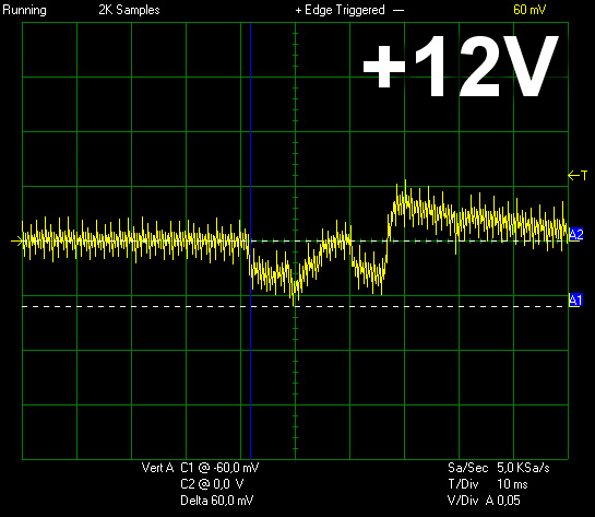
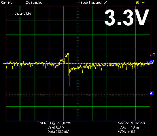
Voltage drops on +12V and 5V are pretty small. On the contrary 3.3V registered large voltage drops and in the second part of Advanced Transient Tests voltage at this rail went out of ATX spec. However we were pleased to see onl< small voltage drops on the +12V rail, the most significant of all, which also is more likely to be hit by large transient loads.
Below you will find the oscilloscope screenshots that we took during Advanced Transient Testing.
Transient Response at 20% Load
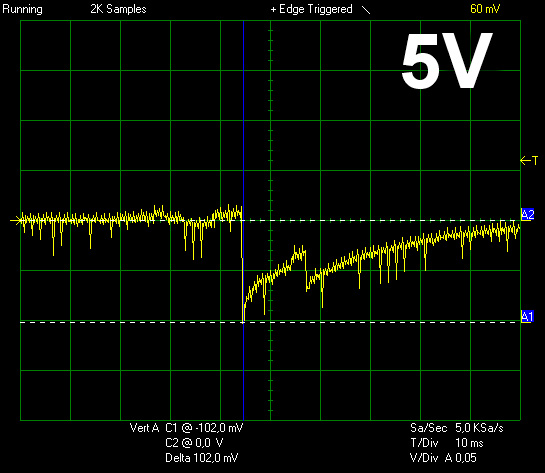
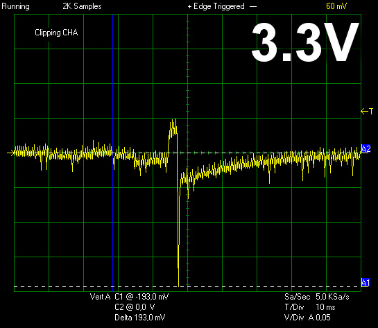
Transient Response at 50% Load


Turn-On Transient Tests
In the next set of tests we measure the response of the PSU in simpler scenarios of transient loads, during the turn on phase of the PSU. In the first test we turn off the PSU, dial 2A load at 5VSB and then switch on the PSU. In the second test, while the PSU is in standby, we dial the maximum load that +12V can handle and we start the PSU. In the final test, while the PSU is completely switched off (we cut off power or switch off the back switch), we dial the maximum load that +12V can handle, we then switch on the PSU from the loader and we restore power. The ATX specification states that recorded spikes on all rails should not exceed 10% of their nominal values (e.g. +10% for 12V is 13.2V and for 5V is 5.5V).

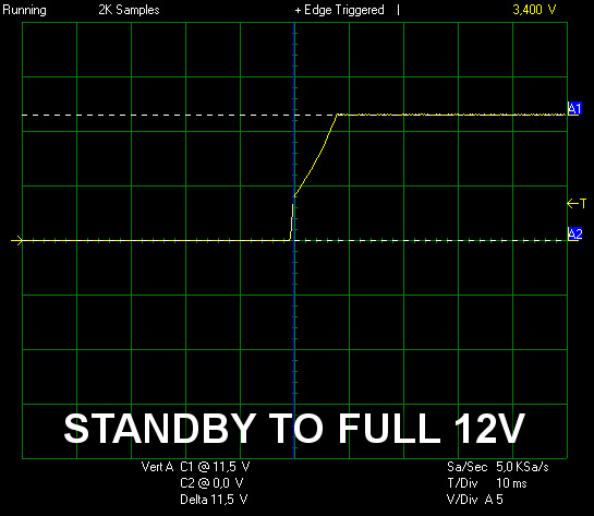
During turn on transient tests 5VSB and +12V registered small spikes that were well below ATX limits.
May 16th, 2024 08:42 EDT
change timezone
Latest GPU Drivers
New Forum Posts
- Double radiator setup with GPU fans on top (10)
- AIO Water Cooler vs Tower Air Cooler (26)
- Ads in forums. under news (11)
- Would you pay more for hardware with AI capabilities? (22)
- EULA in Games (18)
- Post Your TIMESPY, PCMARK10 & FIRESTRIKE SCORES! (2019) (220)
- Ubuntu 24.04 LTS released (31)
- Homeworld 3 [Official Thread] (42)
- What's your latest tech purchase? (20533)
- Unknown Subvendor in GPU-Z (2)
Popular Reviews
- Homeworld 3 Performance Benchmark Review - 35 GPUs Tested
- Enermax REVOLUTION D.F. X 1200 W Review
- Lofree Edge Ultra-Low Profile Wireless Mechanical Keyboard Review
- Upcoming Hardware Launches 2023 (Updated Feb 2024)
- ZMF Caldera Closed Planar Magnetic Headphones Review
- AMD Ryzen 7 7800X3D Review - The Best Gaming CPU
- Corsair MP700 Pro SE 4 TB Review
- ASUS Radeon RX 7900 GRE TUF OC Review
- ThundeRobot ML903 NearLink Review
- Sapphire Radeon RX 7900 GRE Pulse Review
Controversial News Posts
- Intel Statement on Stability Issues: "Motherboard Makers to Blame" (267)
- AMD to Redesign Ray Tracing Hardware on RDNA 4 (227)
- Windows 11 Now Officially Adware as Microsoft Embeds Ads in the Start Menu (172)
- NVIDIA to Only Launch the Flagship GeForce RTX 5090 in 2024, Rest of the Series in 2025 (152)
- AMD Hits Highest-Ever x86 CPU Market Share in Q1 2024 Across Desktop and Server (137)
- AMD RDNA 5 a "Clean Sheet" Graphics Architecture, RDNA 4 Merely Corrects a Bug Over RDNA 3 (127)
- AMD's RDNA 4 GPUs Could Stick with 18 Gbps GDDR6 Memory (114)
- AMD Ryzen 9 7900X3D Now at a Mouth-watering $329 (104)