 3
3
EVGA SuperNOVA GS 650 W Review
Ripple Measurements »Advanced Transient Response Tests
In these tests, we monitor the PSU's response in two different scenarios. First, a transient load (10 A at +12V, 5 A at 5V, 5 A at 3.3V, and 0.5 A at 5VSB) is applied to the PSU for 200 ms while the latter is working at 20% load. In the second scenario, the PSU, while working at 50% load, is hit by the same transient load. In both tests, we measure the voltage drops the transient load causes using our oscilloscope. The voltages should remain within the regulation limits defined by the ATX specification. We must stress here that these tests are crucial since they simulate transient loads a PSU is very likely to handle (e.g., booting a RAID array, an instant 100% load of CPU/VGAs, etc.). We call these tests Advanced Transient Response Tests, and they are designed to be very tough to master, especially for a PSU with a capacity below 500 W.| Advanced Transient Response 20% | ||||
|---|---|---|---|---|
| Voltage | Before | After | Change | Pass/Fail |
| 12 V | 12.091V | 11.942V | 1.23% | Pass |
| 5 V | 5.039V | 4.912V | 2.52% | Pass |
| 3.3 V | 3.362V | 3.246V | 3.45% | Pass |
| 5VSB | 5.068V | 5.033V | 0.69% | Pass |
| Advanced Transient Response 50% | ||||
|---|---|---|---|---|
| Voltage | Before | After | Change | Pass/Fail |
| 12 V | 12.018V | 11.885V | 1.11% | Pass |
| 5 V | 5.000V | 4.867V | 2.66% | Pass |
| 3.3 V | 3.324V | 3.197V | 3.82% | Pass |
| 5VSB | 5.022V | 4.989V | 0.66% | Pass |
We were hoping the +12V rail wouldn't deviate by more than 1%, which the 650 GS wasn't able to pull off. However, deviations on 5V and 5VSB were low enough. The 3.3V rail's performance was average in both tests.
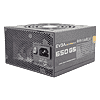
Below are the oscilloscope screenshots we took during Advanced Transient Response testing.
Transient Response at 20% Load
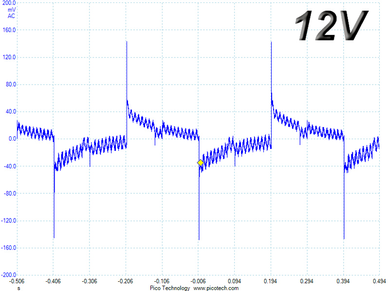


Transient Response at 50% Load


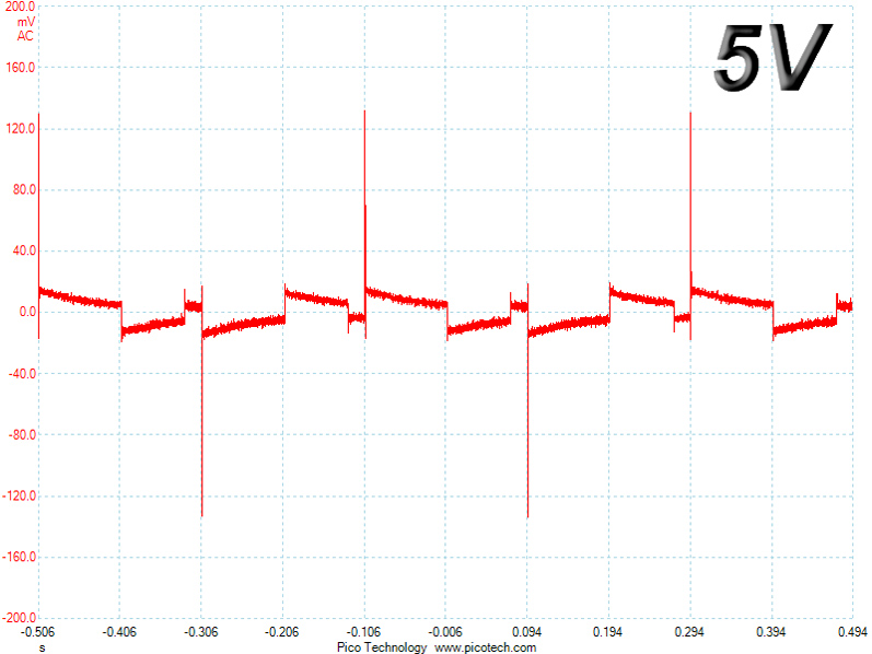
Turn-On Transient Tests
We measure the response of the PSU in simpler scenarios of transient load—during the power-on phase of the PSU—in the next set of tests. In the first test, we turn the PSU off, dial the maximum current 5VSB can output, and switch on the PSU. In the second test, we dial the maximum load +12V can handle and start the PSU while the PSU is in standby mode. In the last test, while the PSU is completely switched off (we cut off power or switch the PSU off by flipping its on/off switch), we dial the maximum load the +12V rail can handle before switching the PSU on from the loader and restoring power. The ATX specification states that recorded spikes on all rails should not exceed 10% of their nominal values (e.g., +10% for 12V is 13.2V, and 5.5V for 5V).

We didn't notice any spikes or large steps or waves on the rails in the first two tests; however, we did notice a period with increased ripple and a notable drop in voltage before it settled down in the third test.
Apr 23rd, 2024 01:34 EDT
change timezone
Latest GPU Drivers
New Forum Posts
- The TPU UK Clubhouse (24764)
- Why MS buying all of these Studios is bad for Gaming (12)
- Linus watercools (56)
- ASRock Deskmini Owner's Club (27)
- The best *budget* ATX PC case on the market? (20)
- TPU's Nostalgic Hardware Club (18459)
- AMD RX 7000 series GPU Owners' Club (1086)
- Embracer Group is breaking into 3 smaller companies... lol who saw this coming, what a joke (7)
- EK seems to be having major issues (22)
- Which new games will you be buying? (292)
Popular Reviews
- Horizon Forbidden West Performance Benchmark Review - 30 GPUs Tested
- Fractal Design Terra Review
- Corsair 2000D Airflow Review
- Thermalright Phantom Spirit 120 EVO Review
- Minisforum EliteMini UM780 XTX (AMD Ryzen 7 7840HS) Review
- ASUS GeForce RTX 4090 STRIX OC Review
- NVIDIA GeForce RTX 4090 Founders Edition Review - Impressive Performance
- ASUS GeForce RTX 4090 Matrix Platinum Review - The RTX 4090 Ti
- Creative Pebble X Plus Review
- MSI GeForce RTX 4090 Gaming X Trio Review
Controversial News Posts
- Sony PlayStation 5 Pro Specifications Confirmed, Console Arrives Before Holidays (115)
- NVIDIA Points Intel Raptor Lake CPU Users to Get Help from Intel Amid System Instability Issues (105)
- AMD "Strix Halo" Zen 5 Mobile Processor Pictured: Chiplet-based, Uses 256-bit LPDDR5X (101)
- US Government Wants Nuclear Plants to Offload AI Data Center Expansion (98)
- Windows 10 Security Updates to Cost $61 After 2025, $427 by 2028 (84)
- Developers of Outpost Infinity Siege Recommend Underclocking i9-13900K and i9-14900K for Stability on Machines with RTX 4090 (82)
- TechPowerUp Hiring: Reviewers Wanted for Motherboards, Laptops, Gaming Handhelds and Prebuilt Desktops (74)
- Intel Realizes the Only Way to Save x86 is to Democratize it, Reopens x86 IP Licensing (70)