 5
5
FSP Aurum PT Series 1200 W Review
Load Regulation, Hold-up Time & Inrush Current »A Look Inside & Component Analysis
Before reading this page, we strongly suggest a look at this article, which will help you understand the internal components of a PSU much better. Our main tool for the disassembly of the PSU is a Thermaltronics TMT-9000S soldering and rework station. It is of extreme quality and is equipped with a matching de-soldering gun. With such equipment in hand, breaking apart every PSU is like a walk in the park!

| FSP PT-1200FM Parts Description | |
|---|---|
| Primary Side | |
| Transient Filter | 4x Y caps, 3x X caps, 2x CM chokes, 1x MOV |
| Bridge Rectifier(s) | 2x LL25XB60 |
| Inrush Current Protection | NTC Thermistor & Relay |
| APFC Mosfets | 4x Infineon IPA60R190P6 |
| APFC Boost Diode | 2x CREE C3D06060A |
| Hold-up Cap(s) | 2x Nippon Chemi-Con (420V, 470uF each, 105°C, KMQ) |
| Main Switchers | 4x STFI26NM60N |
| APFC Controller | Infineon ICE2PCS01 |
| Switching Controller | Champion CM6901T |
| Topology | Full-Bridge |
| Secondary Side | |
| +12V | 8x Infineon BSC014N04LS |
| 5V & 3.3V | DC-DC Converters: 6x Infineon BSC0901NS PWM Controller: APW7159 |
| Filtering Capacitors | Electrolytics (105°C: Chemi-Con (KZE), Rubycon Polymers: Chemi-Con |
| Supervisor IC | SITI PS223H |
| Fan Model | Power Logic PLA13525S12M (12 V, 0.40 A, 111.1 CFM, 41.6 dBA, Hydro Dynamic Bearing) |
| 5VSB Circuit | |
| Rectifying Mosfet | AUIRFR1018E |
| Standby PWM Controller | TinySwitch-III TNY279PN |
| -12V Circuit | |
| PWM Controller | APW7174 |


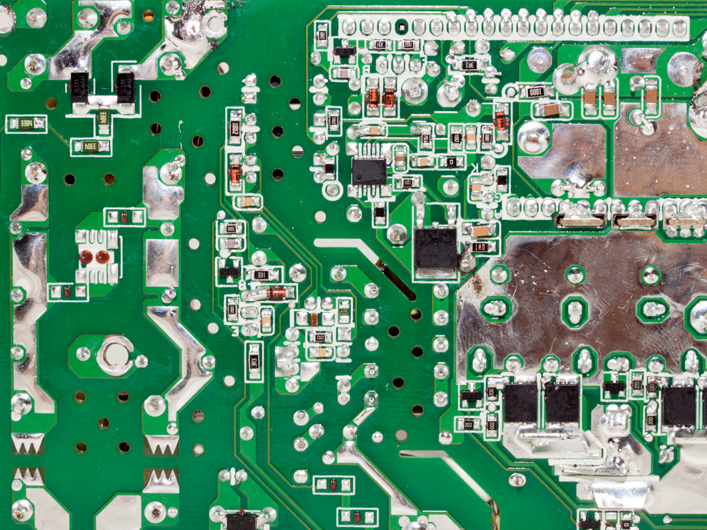
The platform is new and its primary side uses a full-bridge topology with an LLC resonant converter for increased efficiency. The secondary side uses DC-DC converters for the generation of the minor rails. The +12V mosfets are installed on the solder side of the main PCB, and the PSU's casing plays a crucial role in cooling these. The cooling method has lately become pretty popular with high-end platforms since several manufacturers have picked this particular spot on the mainboard's solder side for their +12V fets. The -12V rail's VRM made quite an impression since even cutting-edge PSUs lack such a VRM. FSP was apparently looking to create a top-notch platform, and judging by its design and the components used, it looks as though they have done so successfully. However, our test results will provide us with the full picture.
An X and two Y caps at the AC receptacle form the first part of the EMI filter. The other parts of the filter are on the main PCB and include two X and two Y caps, a pair of CM chokes, and an MOV.


Both bridge rectifiers (LL25XB60) are bolted to a dedicated heatsink. Their quality is top notch, and their combined maximum output reaches 50 A, which easily meets the needs of this unit.

An NTC thermistor and its corresponding relay are depicted above. The thermistor protects the unit against large inrush currents and the relay allows it to cool down quickly.


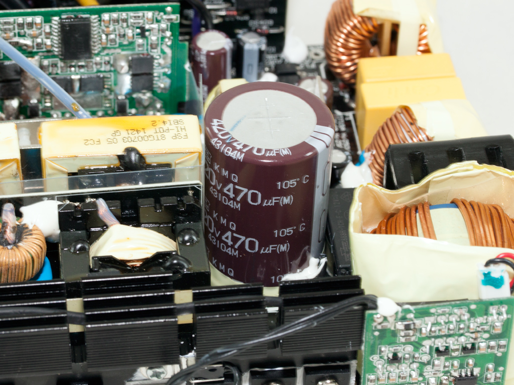

The APFC converter consists of four Infineon IPA60R190P6 fets and a pair of CREE C3D06060A boost diodes. The bulk caps are provided by Chemi-Con (420 V, 470 uF each or 940 uF combined, 105°C, KMQ series), and their combined capacity looks low for a 1.2 kW PSU.


The APFC controller is an Infineon ICE2PCS01, installed on a daughter-board close to the APFC converter. On the front of the same board are a KA363A IC and an LM358N IC, with the latter integrating two operational amplifiers.

The main switchers, probably arranged in a full-bridge topology, are four STFI26NM60N fets.


The LLC resonant controller, a Champion CM6901T, is on a vertical PCB in the primary side. The same boards also hosts an LM339N quad comparator and an LM358N dual-operational amplifier.

On the main PCB's primary side are two Silicon Labs Si8233BD isolator interfaces.


Both DC-DC converters are installed on the same daughter-board. Their common PWM controller is an Anpec APW7159, and a total of six Infineon BSC0901NS mosfets are used by both VRMs. Their markings partially erased, we were only able to identify these because of our Canon 60mm macro lens.


The mosfets rectifying the +12V rail are on the solder side of the PCB. Eight Infineon BSC014N04LS mosfets are used for this purpose.


FSP didn't compromise on the caps it elected. The PT-1200FM only uses Japanese caps, mostly provided by Chemi-Con. We also spotted a few electrolytic caps by Rubycon. All electrolytic caps in the secondary side are rated at 105°C, and these are for filtering the +12V rail.


The protections IC found on this vertical PCB is a SITI PS223H with OTP (Over Temperature Protection) out of the box, along with OCP for two +12V rails. However, this unit only has a single +12V rail.

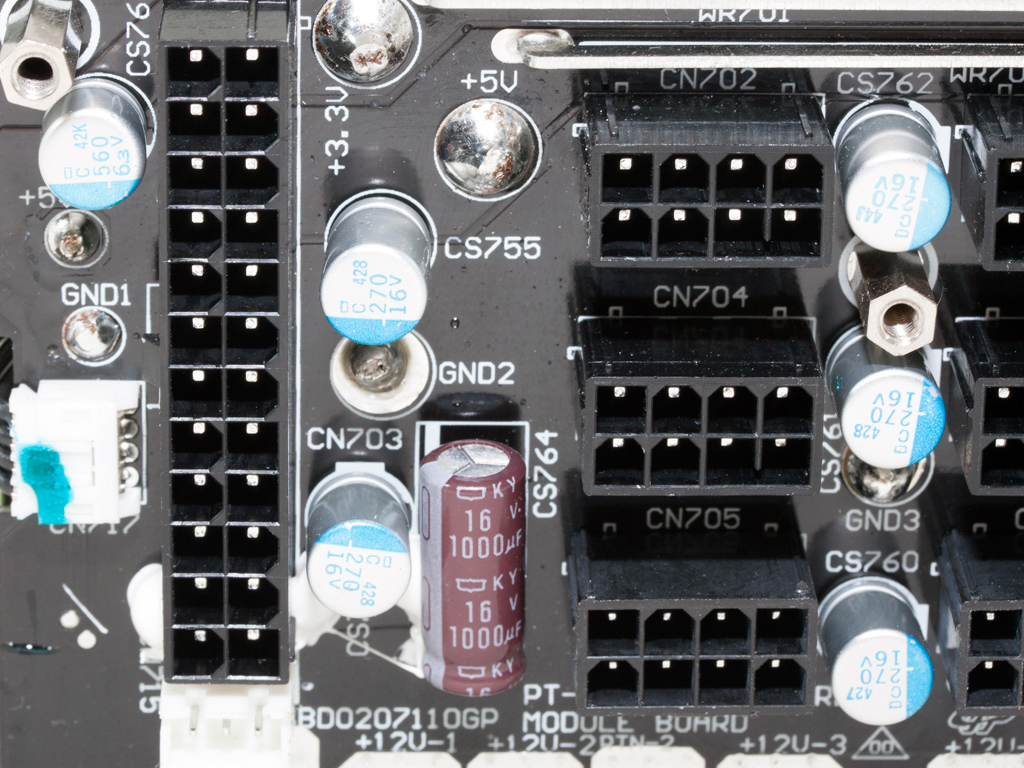

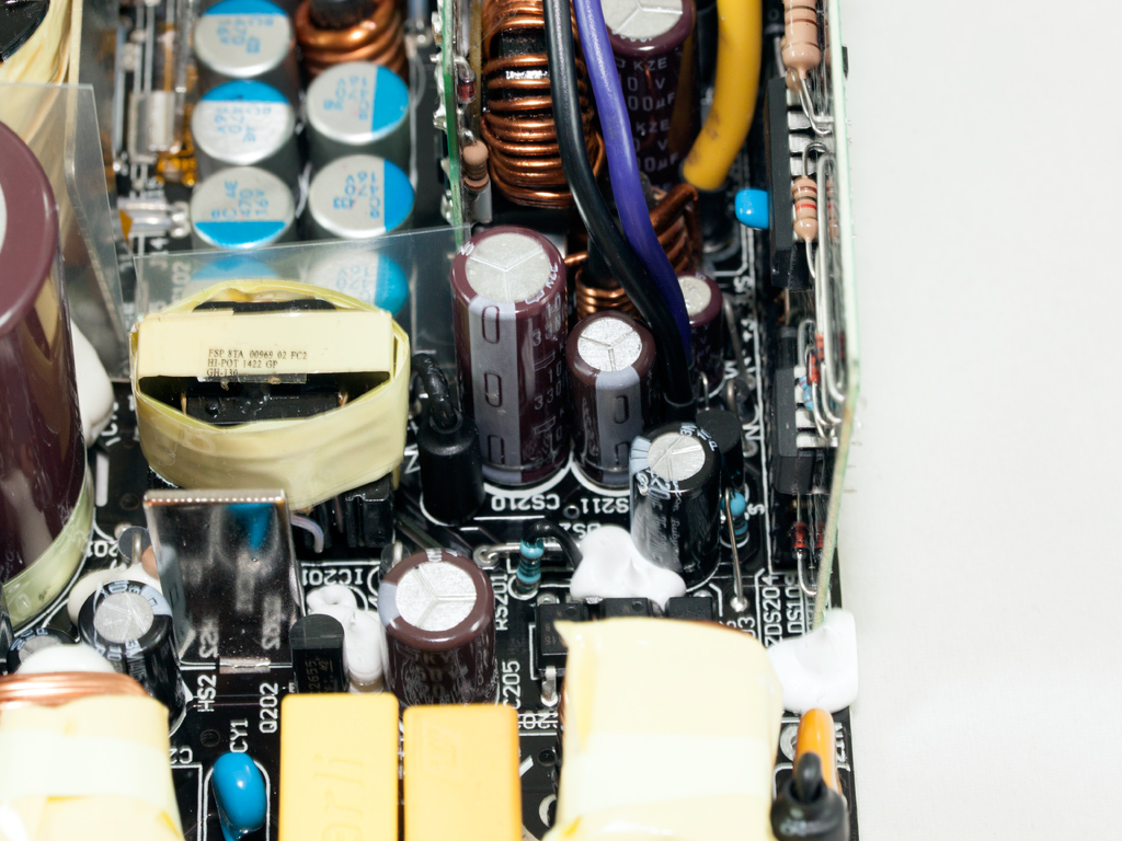
Many Chemi-Con polymer caps on the modular PCB's primary side provide some extra ripple filtering for all rails.
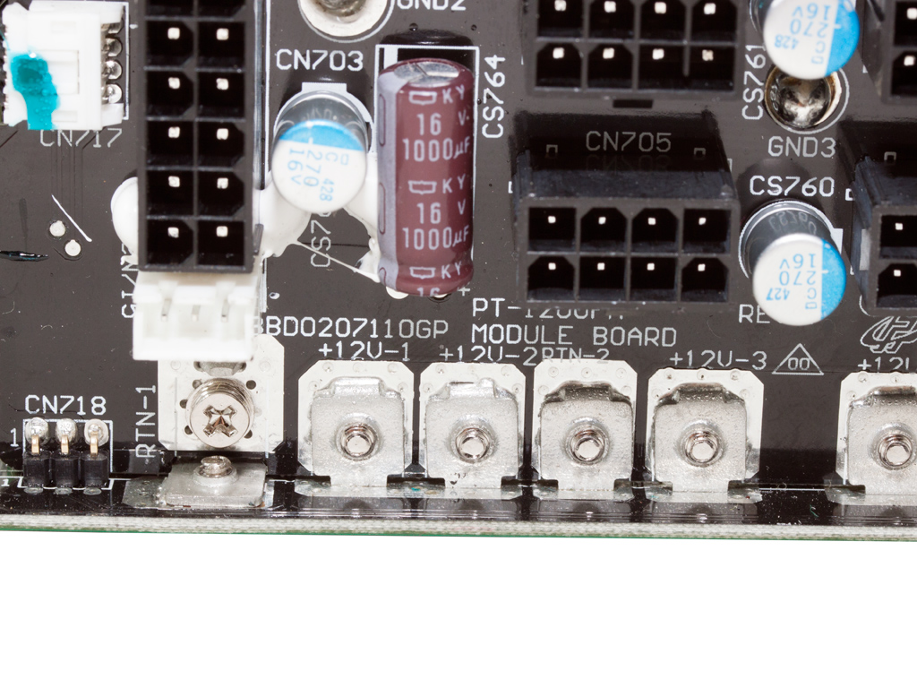

To minimize energy losses, several bus bars transfer power to the modular PCB.


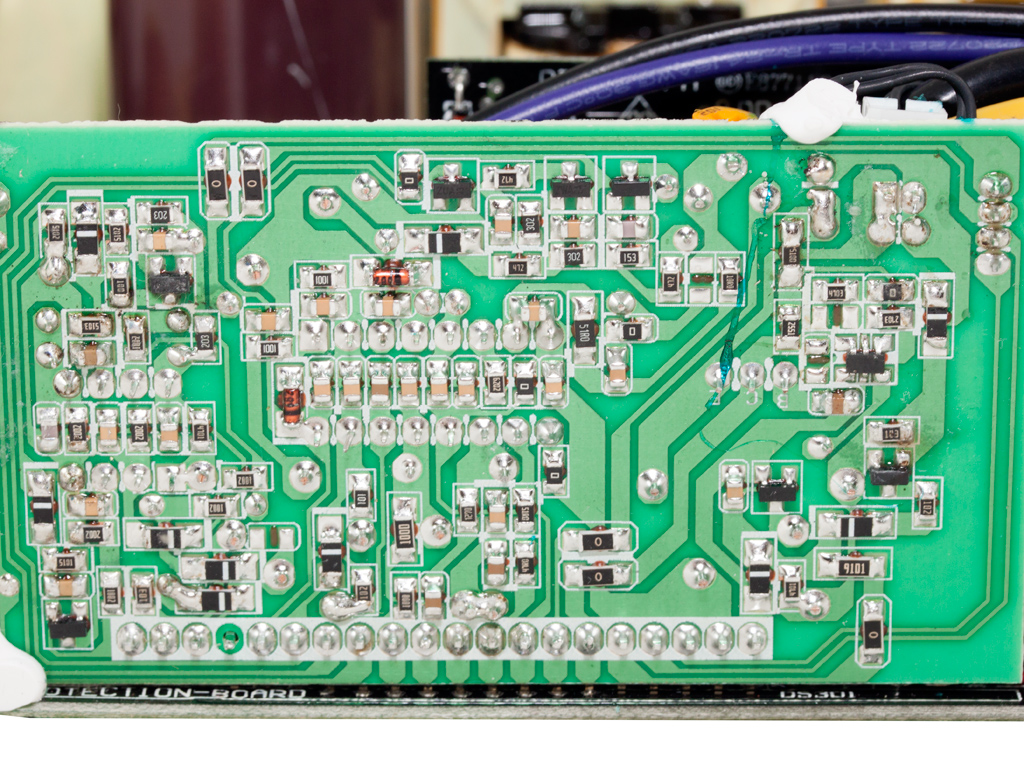
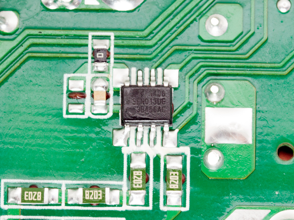
This small board hosts an APW7174 PWM controller on its solder side. Its purpose is most likely to generate the -12V rail. It is very rare to see a dedicated VRM for this by now practically useless rail.
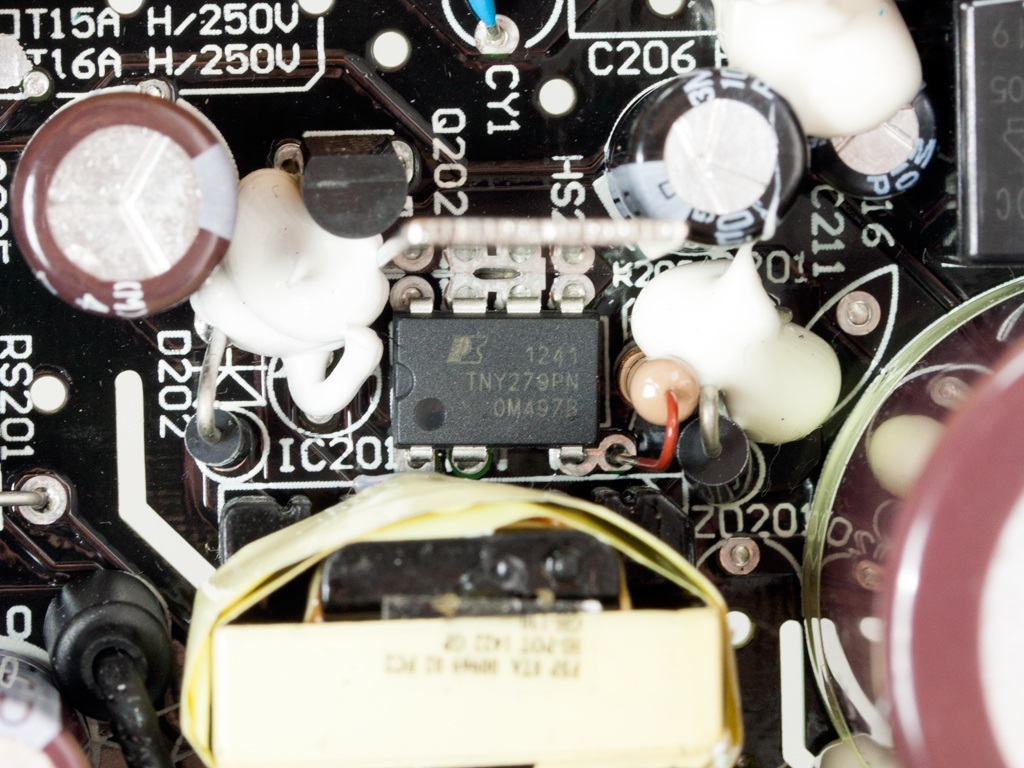

The standby PWM controller is a TinySwitch-III TNY279PN, and an AUIRFR1018E mosfet on the rear of the mainboard rectifies the 5VSB rail. We expect the 5VSB rail to be very efficient since a mosfet instead of a less efficient SBR is used.
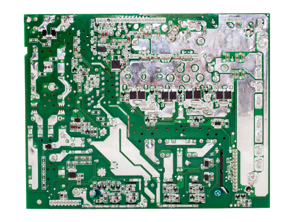
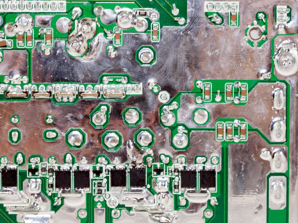


Soldering quality is very good, and not even a couple poor soldering joints spoiled the overall nice impression. FSP did a fine job here, and the PCB'S finish is excellent as well.
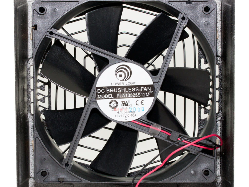

The cooling fan is by Power Logic (PLA13525S12M, 135 mm, 12 V, 0.4 A, 111.1 CFM, 41.6 dBA), and FSP says it to use a Hydro Dynamic Bearing, which is the best type of bearing available today. The fan's official specifications claim its maximum RPM to be 2000, but we measured an RPM of 2200 at 12 VDC.
May 7th, 2024 00:19 EDT
change timezone
Latest GPU Drivers
New Forum Posts
- Only some humans can see refresh rates faster than others, I am one of those humans. (202)
- The Official Thermal Interface Material thread (1169)
- What's your latest tech purchase? (20450)
- GPU Hot Spot Temperature 105 Celsius, fans at 3000 RPM, while GPU Temperature is max 70 Celsius (40)
- Cybersecurity - OSINT Software for Linux (3)
- Gigabyte Aorus Elite AX V2 rev 1.1 BIOS update "AMD AGESA V2 1.2.0.B" (5)
- nvflashk - Flash any BIOS to NVIDIA GPUs - Safe board ID bypass up to 4xxx series (241)
- RTX 2070 8GB unable to flash (0)
- Update on the whole PC rebooting issue. There was an extra standoff in the case, but now it's crashing even more (3)
- Battery swap for cyberpower UPS (61)
Popular Reviews
- Finalmouse UltralightX Review
- Cougar Hotrod Royal Gaming Chair Review
- Meze Audio LIRIC 2nd Generation Closed-Back Headphones Review
- Upcoming Hardware Launches 2023 (Updated Feb 2024)
- Corsair iCUE Link RX120 RGB 120 mm Fan Review
- ASRock NUC BOX-155H (Intel Core Ultra 7 155H) Review
- AMD Ryzen 7 7800X3D Review - The Best Gaming CPU
- ASUS Radeon RX 7900 GRE TUF OC Review
- Montech Sky Two GX Review
- HYTE THICC Q60 240 mm AIO Review
Controversial News Posts
- Intel Statement on Stability Issues: "Motherboard Makers to Blame" (248)
- Windows 11 Now Officially Adware as Microsoft Embeds Ads in the Start Menu (167)
- AMD to Redesign Ray Tracing Hardware on RDNA 4 (166)
- Sony PlayStation 5 Pro Specifications Confirmed, Console Arrives Before Holidays (118)
- AMD's RDNA 4 GPUs Could Stick with 18 Gbps GDDR6 Memory (114)
- NVIDIA Points Intel Raptor Lake CPU Users to Get Help from Intel Amid System Instability Issues (106)
- NVIDIA to Only Launch the Flagship GeForce RTX 5090 in 2024, Rest of the Series in 2025 (105)
- AMD Ryzen 9 7900X3D Now at a Mouth-watering $329 (104)