 45
Thermal Grizzly WireView Pro Review
Screen Modes »Disassembly

The PCB is dominated by the 16-pin inputs and outputs. We can also clearly see the two small 2-pin connections for the thermal probes. Next to them is a four pin connector that's unused, I suspect it is an SPI header that's used during manufacturing to flash the microcontroller with its firmware.
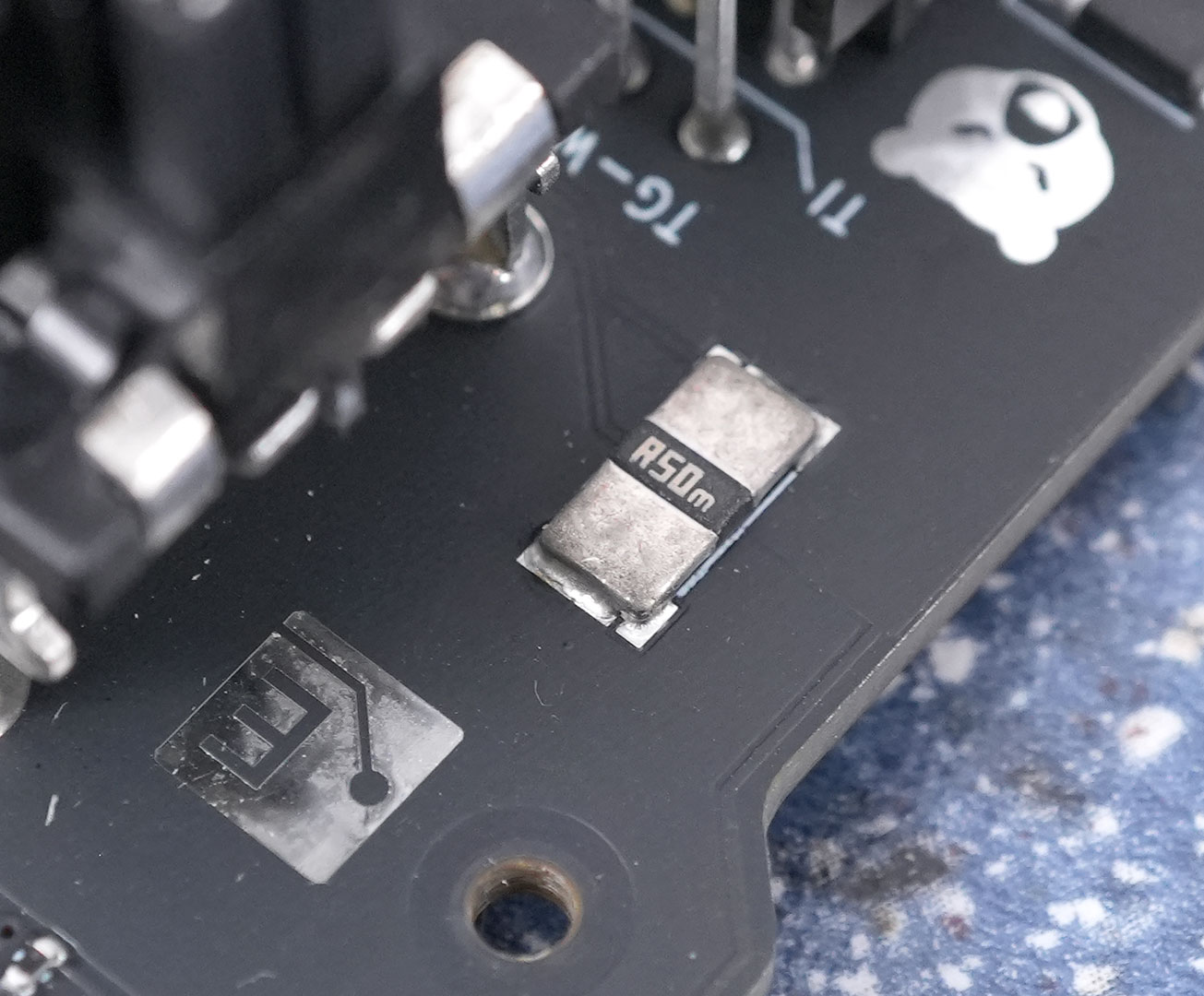
Here we can see one of the two current shunts that are used for the measurements. The principle of operation is that all current runs across small resistors (2x 50 milliOhms). This resistance causes a voltage drop that's proportional to the current flowing through the resistor (Ohm's law). So; measure the voltage drop across the resistor, measure the voltage, then multiply the numbers to calculate power.
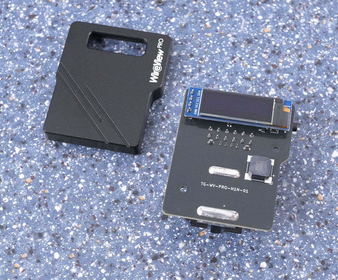
Removing the metal cap doesn't reveal much.
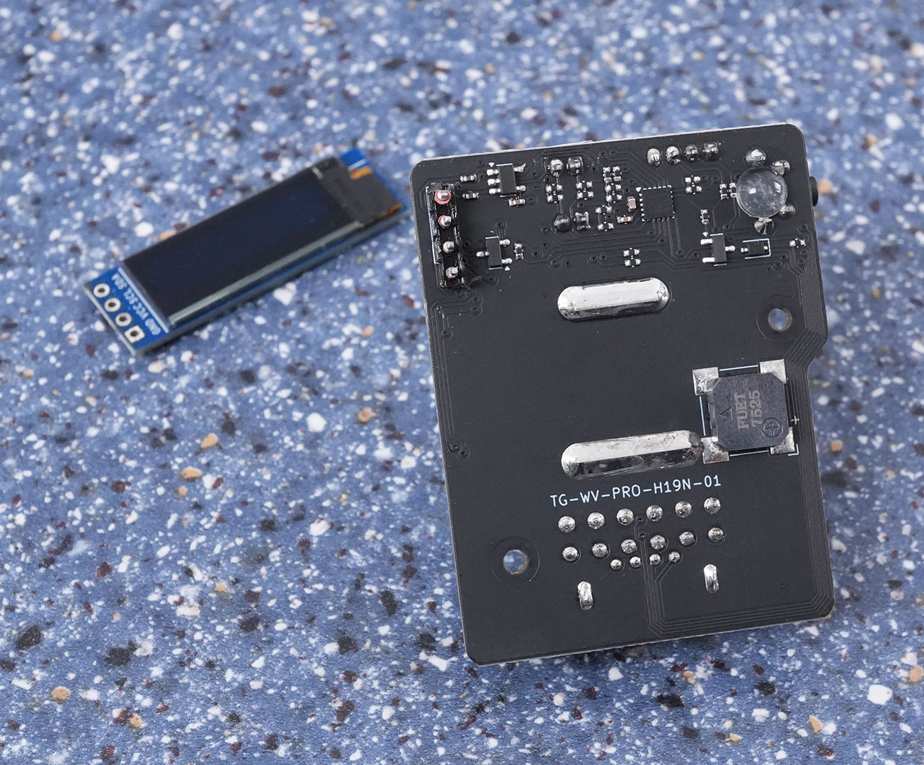
The good stuff is under the display, so I desoldered it. Now we see some new components.
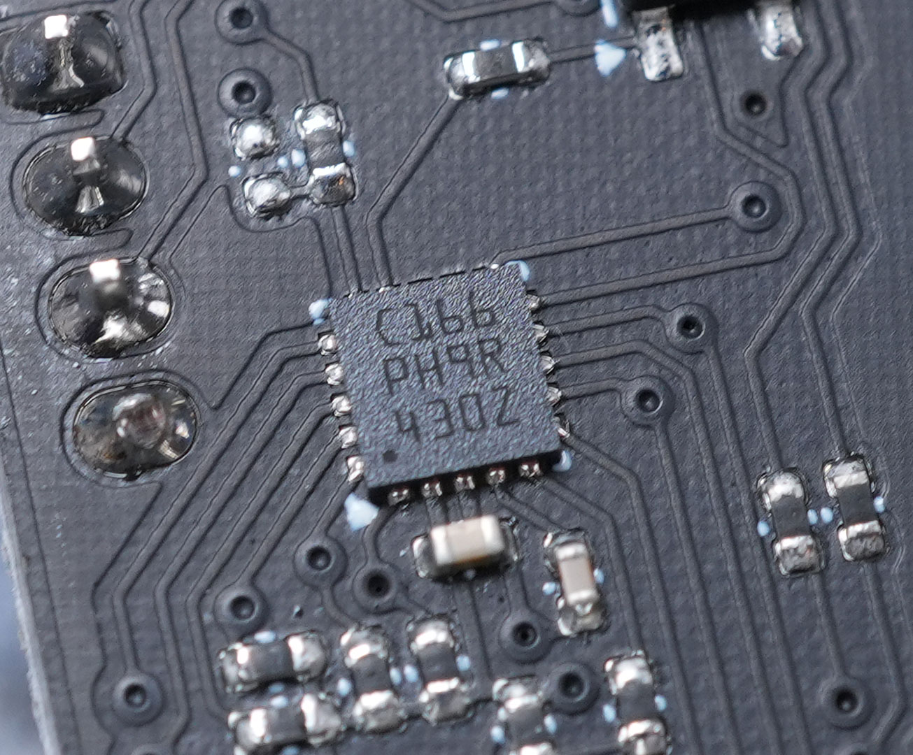
This is the microcontroller, the heart of the WireView Pro. Think of it like a very compact processor, it's probably an 8-bit or 16-bit design running highly specialized assembler code.
Nov 21st, 2026 06:50 PST
change timezone
Latest GPU Drivers
New Forum Posts
- What's your latest tech Freebie? (87)
- UPS what one to get? (3)
- Differences i might've missed between these ultrawides to decide which to buy during BF. (0)
- Honestly, do you care about GTA VI? (220)
- Anthrophics IPO (31)
- Without Jensen, PC gaming will be (53)
- WarpCoreBench scores! (88)
- TPU's Nostalgic Hardware Club (22179)
- [Poll] 12V-2x6 Connector Protection: What Are You Using? (WireView / Ampinel / Equalizer / Other / Nothing) (50)
- Windows 11 General Discussion (7743)
Popular Reviews
- Microsoft Surface Laptop Ultra Review - The Next-gen Arm Laptop
- Ugreen NASync DXP4800 GT Review
- Corsair RM1200e (Second Generation) Review
- Pulsar Office Tour & First Look at P1 Dual-Sensor Mouse
- Upcoming Hardware Launches 2027 (Updated Nov 2026)
- Acemagic Retro X3 Review
- Biwin Black Opal NV7400 2 TB Review
- AMD Ryzen 7 9800X3D Review - The Best Gaming Processor
- AMD Zen 6 Technical Deep Dive
- Chieftec Iceberg PRO 360 DARK Review
TPU on YouTube
Controversial News Posts
- NVIDIA Co-Founder and CEO Jensen Huang Officially Resigns (491)
- Report: Jensen Huang Eyes NVIDIA Comeback (258)
- Open Letter Asking NVIDIA to Reinstate Jensen Huang Passes 115,000 Signatures (184)
- OpenAI CEO Argues Home PCs Waste the World's Limited DRAM Supply (152)
- NVIDIA Launches Investigation Into Jensen Huang's Relationship With Suspected Chinese Spy (136)
- Intel "Raptor Lake Next" 16-Core and 20-Core CPUs Surface (130)
- Legendary Game Studio BioWare Shuts Down Following EA Layoffs (104)
- NVIDIA GeForce RTX 50-Series Scheduled for up to $500 Price Hike This Week (89)