 1
1
Thermaltake Toughpower XT Gold 1375 W Review
Voltage Regulation & Efficiency »A Look Inside
Before reading this page, we strongly suggest to take a look at this article, which will help you understand much better the internal components of a PSU.
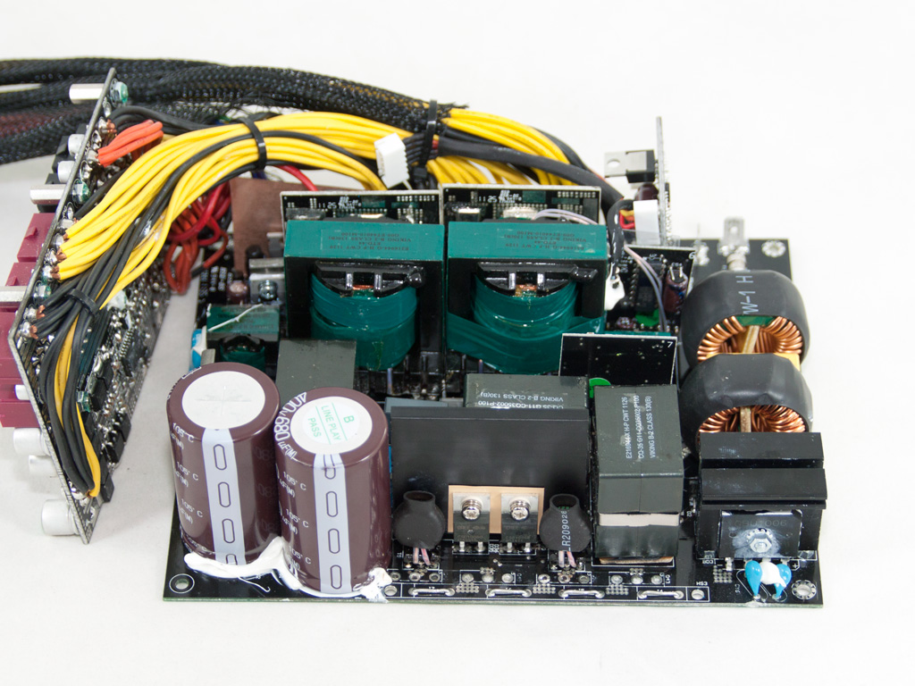


The OEM of this unit is Channel Well Technology or CWT, and in order to achieve high efficiency and performance, of course, cutting-edge technology was utilized in this new platform, named PUO. This, however, has a big effect on the final price, judging from the PSU's stiff retail price. Briefly, a full bridge topology and an LLC converter are used on the primary side, while synchronous rectification (SR) along with two VRMs for the generation of the minor rails are utilized in the secondary side. To provide you with a clearer view of the internals, we removed the APFC and primary heatsinks, a fairly easy task for the Hakko 808.
As usual, the transient filtering stage starts at the AC receptacle and, in this case, we find one X and two Y caps installed. It continues on to the main PCB with two CM chokes, an MOV, and two X and two pairs of Y caps, with the second pair located after the bridge rectifiers.


There are three parallel bridge rectifiers (GBU1006), bolted on to two dedicated heatsinks.


The APFC utilizes an interleaved design, in which two APFC converters operate in parallel with a phase difference among them. This leads to minimized input/output current ripple, lower conduction losses, higher efficiency, and doubling of the effective switching frequency. Each APFC converter uses an SPW35N60C3 mosfet and a CREE CSD10060 boost diode. Next to each boost diode, there is a current transformer (wrapped in heat-shrink tubing), one for each APFC converter. Finally, the hold-up caps are two parallel Nippon Chemi-Con (400 V, 680 µF, 105°C, KMR series).

The PFC controller is installed on a vertical daughter-board, and, unfortunately, we couldn't identify its model number, since its markings were totally erased. Nevertheless, most likely it's the same as that used in TPX-1275M, which is a UCC28070 IC.

Between the resonant tank and one of the transformers used by the APFC circuit, we find a small electromagnetic relay and the thermistor responsible for inrush protection.
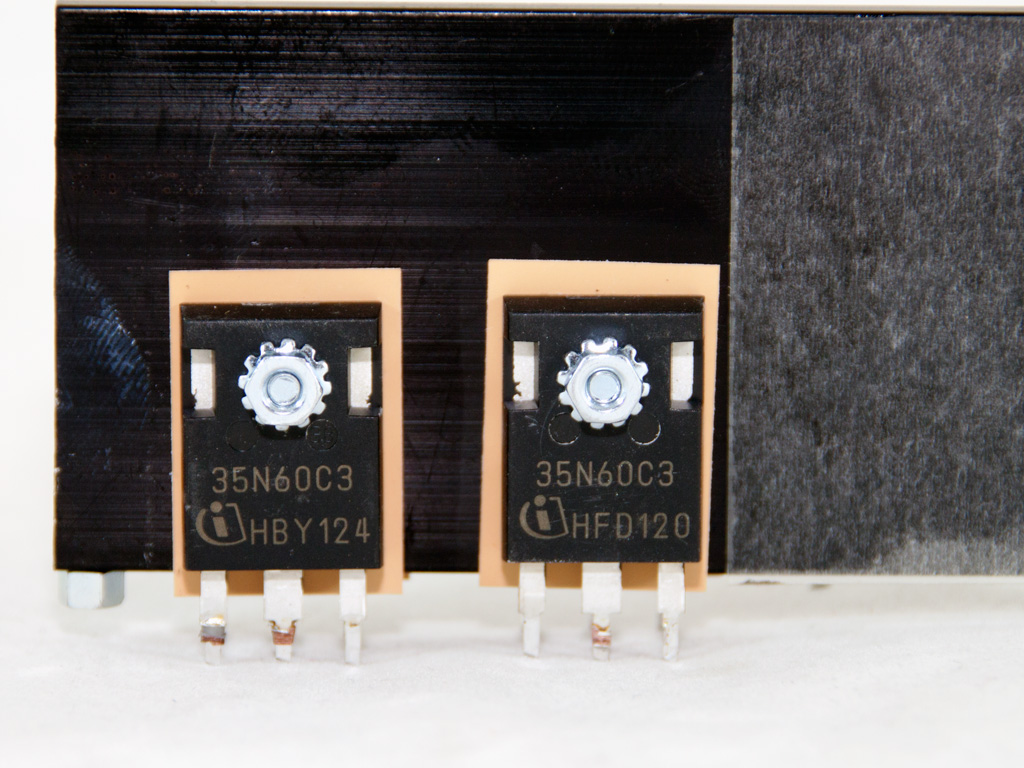

The four main switchers (SPW35N60C3) are arranged into a full bridge topology, which, in conjunction with the LLC converter, provides Zero Voltage Switching (ZVS), thus offering a significant efficiency boost.
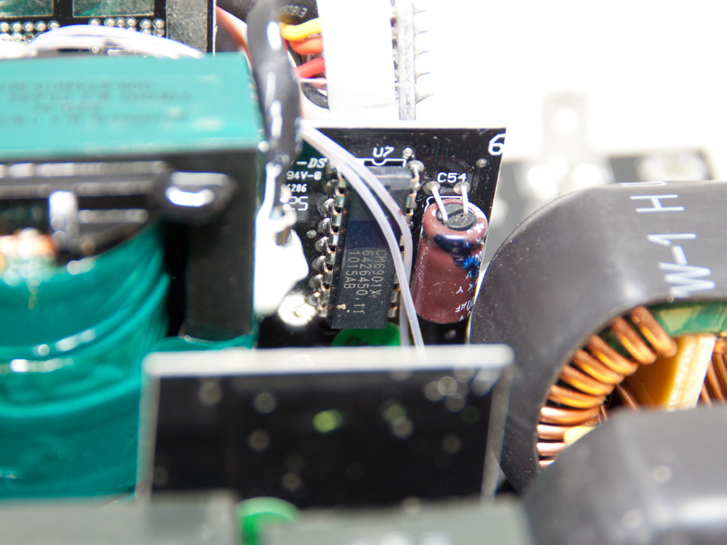
The LLC resonant controller is a CM6901 IC.
Instead of having one big main transformer, there are two smaller parallel main transformers. Strangely enough, the thermistor, responsible for the fan speed control, is attached to one of them. Normally, these thermistors are bolted on to the secondary heatsink, but in this PSU there is no such thing.


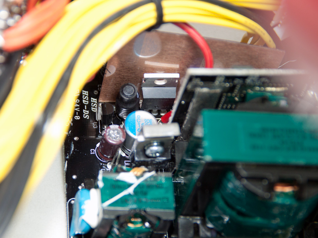
In the secondary side, synchronous rectification is utilized and two vertical PCBs hold all the mosfets that rectify the +12 V rail, twelve IPD031N06L in total. Mainly solid caps, provided by an unknown manufacturer, are used for filtering purposes in the secondary side along with a few electrolytic Nippon Chemi-Cons caps. Also, a single Chemi-Con polymer cap is used in the 5VSB circuit. The latter, most likely, utilizes also an AP72T03GP FET.


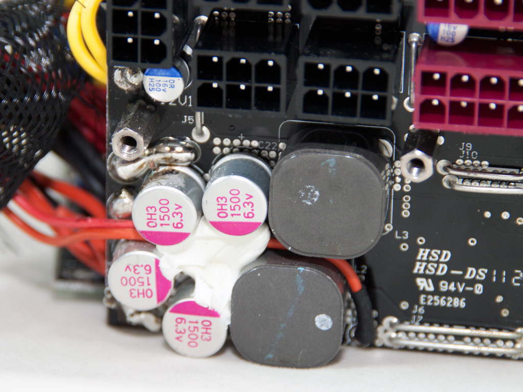

Both VRMs that generate the minor rails are located on the modular PCB, so they directly feed the modular sockets, decreasing this way energy losses, due to voltage drops on the cables. The common PWM controller is an APW7159 IC, while in total four M3004D and four M3006D FETs rectify the rails. At the front of the modular PCB, there are two small inductors, used by the VRMs, and several Enesol polymer caps along with some smaller, unknown brand, ones.
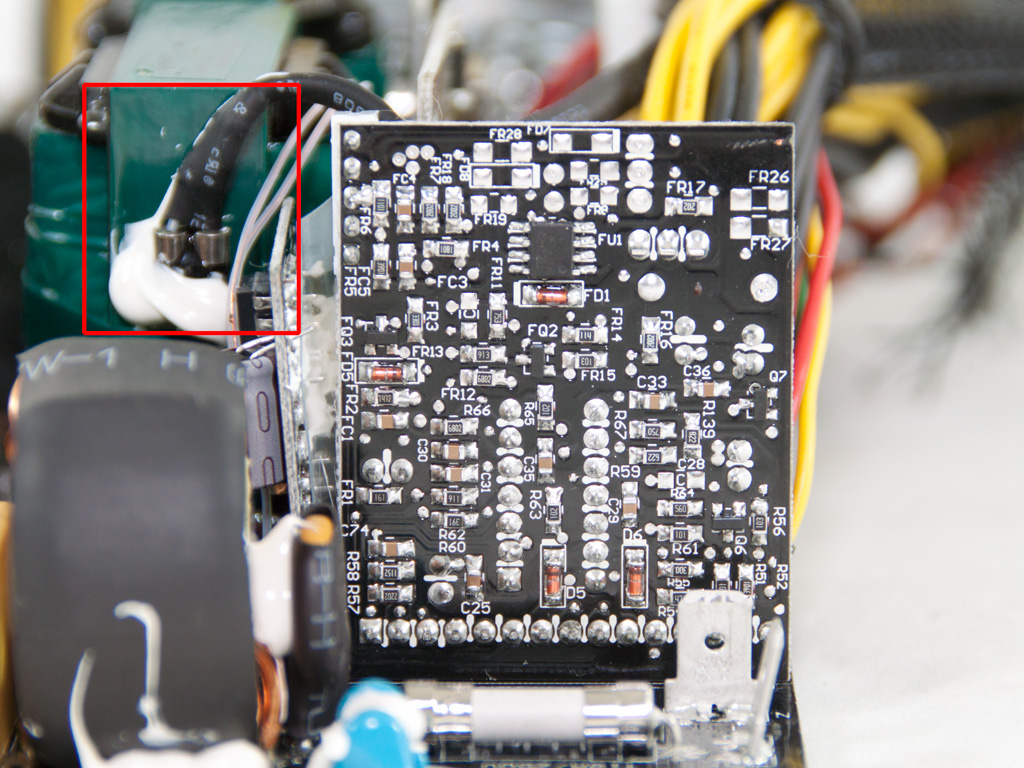

The supervisor IC, a SITI PS229 IC, is installed on a vertical PCB located on the secondary side. In the first of the above photos, besides the aforementioned PCB, you can also see the thermistor, responsible for the fan speed control, which is attached to one of the main transformers. Since there is no secondary heatsink, the only place to attach this thermistor was the main transformer, which, however, is not an ideal solution since the fan engages rather late and after the ambient temperature has reached very high levels.


Soldering quality on the main PCB is good but definitely not topnotch like in Delta and Seasonic high-end implementations. Nevertheless, we didn't spot any problems at all and all component leads are short.

The S.P.T. PCB.

The cooling fan is provided by Yate Loon and its actual model number is D14BM-12 (12 V, 1400 RPM, 62.0 CFM, 29 dBA), so it can't reach 1900 RPM ± 10% that Thermaltake claims, but, actually, this is a good thing since very high RPMs are unnecessary for such a high-efficiency PSU and, on top of that, they would dramatically increase the noise output. Exactly the same fan is used as in the TPX-1275M.
May 8th, 2024 18:38 EDT
change timezone
Latest GPU Drivers
New Forum Posts
- What's a good option for a digital touchless thermometer? (9)
- Does anyone here overclock their video cards? Is it really worth it? (72)
- Your way of cooling your PC? (35)
- TPU's Nostalgic Hardware Club (18503)
- Ubuntu 24.04 LTS released (3)
- POLL: Can you see the difference past 60fps (gaming/other) (58)
- not impressed - nvme vs ssd (72)
- im new to throttelstop and i think i messed it up by copying others any hints would be very much aprreciated (14)
- Current Sales, Bundles, Giveaways (10229)
- Arkane Austin and Redfall: what happened? (50)
Popular Reviews
- CHERRY XTRFY M64 Pro Review
- Corsair iCUE Link RX120 RGB 120 mm Fan Review
- Finalmouse UltralightX Review
- Bykski CPU-XPR-C-I CPU Water Block Review - Amazing Value!
- Upcoming Hardware Launches 2023 (Updated Feb 2024)
- Cougar Hotrod Royal Gaming Chair Review
- Meze Audio LIRIC 2nd Generation Closed-Back Headphones Review
- AMD Ryzen 7 7800X3D Review - The Best Gaming CPU
- ASRock NUC BOX-155H (Intel Core Ultra 7 155H) Review
- ASUS Radeon RX 7900 GRE TUF OC Review
Controversial News Posts
- Intel Statement on Stability Issues: "Motherboard Makers to Blame" (261)
- AMD to Redesign Ray Tracing Hardware on RDNA 4 (206)
- Windows 11 Now Officially Adware as Microsoft Embeds Ads in the Start Menu (167)
- NVIDIA to Only Launch the Flagship GeForce RTX 5090 in 2024, Rest of the Series in 2025 (142)
- Sony PlayStation 5 Pro Specifications Confirmed, Console Arrives Before Holidays (119)
- AMD's RDNA 4 GPUs Could Stick with 18 Gbps GDDR6 Memory (114)
- NVIDIA Points Intel Raptor Lake CPU Users to Get Help from Intel Amid System Instability Issues (106)
- AMD Ryzen 9 7900X3D Now at a Mouth-watering $329 (104)