 11
11
XPG Core Reactor 750 W Review
(11 Comments) »Introduction
We would like to thank XPG for supplying the review sample.
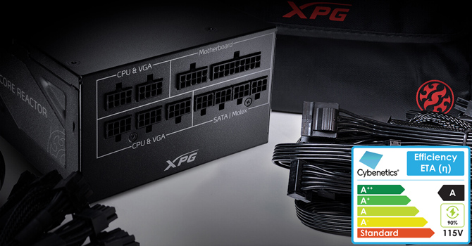
XPG made its debut in the PSU market with the Core Reactor line, which is manufactured by Channel Well Technology and consists of three models with capacities ranging from 650 W to 850 W. All three models are 80 PLUS Gold certified. They have also been certified with respective ETA-A (115 V: 88%–91%, 230 V: 90%–93%) and LAMBDA-A- to LAMBDA-A+ efficiency and noise ratings by Cybenetics.
All Core Reactor models have two EPS connectors, so they are suitable for high-end mainboards, including those equipped with AMD's X570 chipset. A few years ago, only server mainboards required a pair of EPS connectors. However, the comparatively higher CPU core count with today's high-end processors lead to an increase in the power delivery capacity of the corresponding VRMs and, consequently, power consumption. This means a single EPS connector isn't enough anymore, especially for high-end CPUs like the AMD Ryzen 9 3900x and 3950x.
The XPG Core Reactor 750 W has enough capacity to power a potent gaming system (or a video editing workstation). XPG promises a silent operation, and the compact dimensions are a definite advantage of this PSU. At only 140 mm deep, you won't have to worry about whether your chassis will have enough space to accommodate the power supply, and installation will also be easier. That having been said, not all is perfect when it comes to the PSU's installation because the cables aren't all that flexible. The ATX, EPS and PCIe connectors use thicker 16AWG gauges, which means they will give you a hard time during cable management.
Specifications
| Features & Specifications | |
|---|---|
| Max. DC Output | 750 W |
| PFC | Active PFC |
| Efficiency | 80 PLUS Gold, ETA-A |
| Noise | LAMBDA-A (20–25 dBA) |
| Modular | Yes (fully) |
| Intel C6/C7 Power State Support | Yes |
| Operating Temperature | 0–50 °C |
| Protections | Over Voltage Protection Under Voltage Protection Over Power Protection Over Temperature Protection Over Current Protection Short Circuit Protection |
| Cooling | 120 mm fluid dynamic bearing fan (HA1225H12F-Z) |
| Semi-passive Operation | No |
| Dimensions (W x H x D) | 150 mm x 85 mm x 140 mm |
| Weight | 1.41 kg (3.11 lb) |
| Compliance | ATX12V v2.52, EPS 2.92 |
| Warranty | 10 years |
| Price at Time of Review (excl. VAT) | $139.90 |
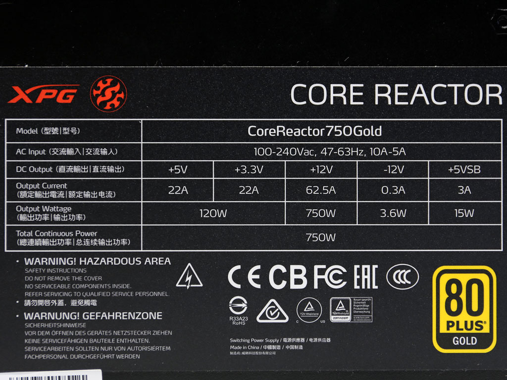
| Power Specifications | |||||||
|---|---|---|---|---|---|---|---|
| Rail | 3.3 V | 5 V | 12 V | 5 VSB | -12 V | ||
| Max. Power | 22 A | 20 A | 62.5 A | 3 A | 0.3 A | ||
| 120 W | 750 W | 15 W | 3.6 W | ||||
| Total Max. Power | 750 W | ||||||
Photos


The box uses a dark backdrop, and the graphics design is kept conservative. Included is a nice pouch, which will prove handy for either storing unused modular cables or other stuff.


The external design is not all that appealing, mostly because of the fan at the center. This was done to increase the impact of airflow to those areas that need it the most.


Dimensions are compact because of the limited depth.
Cables and Connectors
| Modular Cables | ||||
|---|---|---|---|---|
| Description | Cable Count | Connector Count (Total) | Gauge | In Cable Capacitors |
| ATX connector 20+4 pin (650mm) | 1 | 1 | 16-20AWG | No |
| 4+4 pin EPS12V (650mm) | 2 | 2 | 16AWG | No |
| 6+2 pin PCIe (650 mm+150 mm) | 2 | 4 | 16-18AWG | No |
| 6+2 pin PCIe (650 mm) | 2 | 2 | 16AWG | No |
| SATA (500 mm+145 mm+145 mm+145 mm) | 3 | 12 | 18AWG | No |
| 4-pin Molex (500 mm+150 mm+150 mm+150 mm) | 1 | 4 | 18AWG | No |
| AC Power Cord (1400 mm) - C13 coupler | 1 | 1 | 18AWG | - |


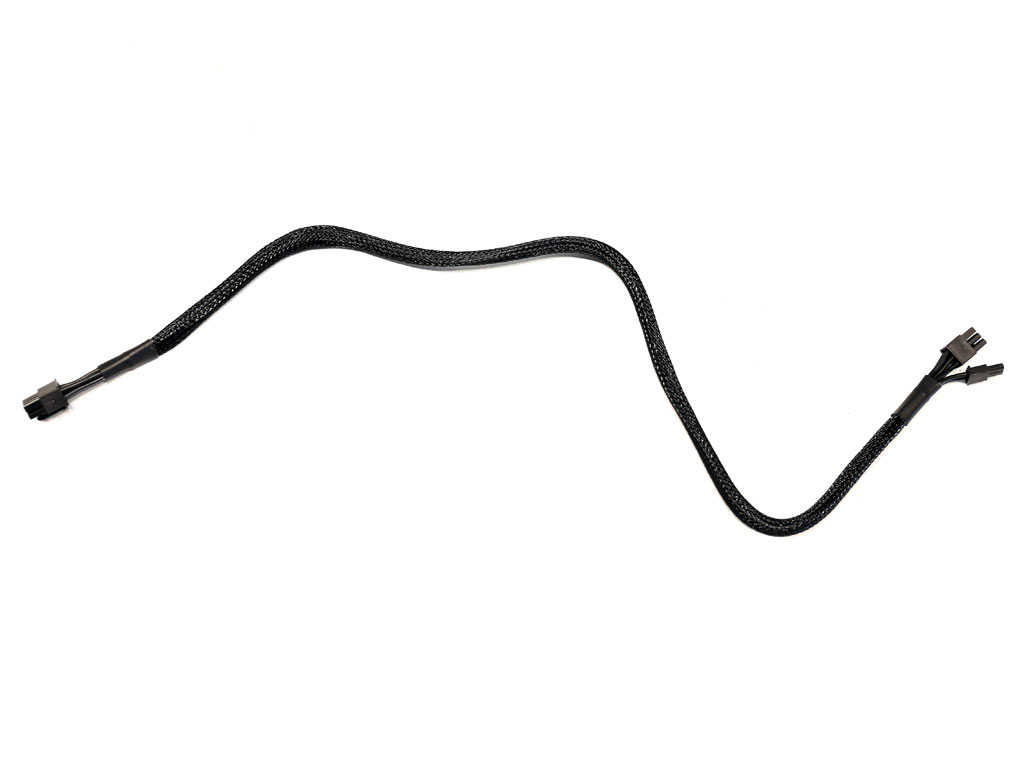
There are plenty of connectors on cables that are long enough. The thick wires for lower voltage drops are the only problem here because they make the cables less flexible. Slightly longer (700 mm or more) EPS cables would be ideal.


The peripheral connectors are far enough apart.
Component Analysis
Before reading this page, we strongly suggest a look at this article, which will help you understand the internals of a PSU better.| XPG Core Reactor 750 W Parts Description | |
|---|---|
| General Data | |
| Manufacturer (OEM) | CWT |
| PCB Type | Double-sided |
| Primary Side | |
| Transient Filter | 4x Y caps, 2x X caps, 2x CM chokes, 1x MOV |
| Bridge Rectifier(s) | 2x GBU15L06 (600 V, 15 A @ 115 °C) |
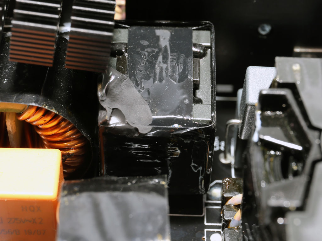
| Inrush Current Protection | NTC Thermistor & Relay |
| APFC MOSFETs | 2x Vishay SiHF30N60E (650 V, 18 A @ 100 °C, 0.125 ohm) & 1x SPN5003 FET (for reduced no-load consumption) |
| APFC Boost Diode | 1x CREE C3D10060A (600 V, 10 A @ 150 °C) |
| Hold-up Cap(s) | 1x Nippon Chemi-Con (420 V, 680 uF, 2,000 h @ 105 °C KMZ) |
| Main Switchers | 2x Vishay SiHF30N60E (650 V, 18 A @ 100 °C, 0.125 ohm) |
| APFC Controller | Champion CM6500UNX |
| Switching Controller | Champion CU6901V |
| Topology | Primary side: Half-bridge & LLC converter Secondary side: Synchronous Rectification & DC-DC converters |
| Secondary Side | |
| +12 V MOSFETs | 8x On Semiconductor NTMFS5C430N (40 V, 131 A @ 100 °C, 1.7 mOhm) |
| +5 V & +3.3 V | DC-DC Converters:
|
| Filtering Capacitors | Electrolytic: |
| Supervisor IC | IN1S313I-SAG |
| Fan Model | Hang Hua HA1225H12F-Z (120 mm, 12 V, 0.58 A, fluid dynamic bearing fan) |
| 5VSB Circuit | |
| Rectifier(s) | Silan Microelectronics SVF4N65RDTR FET (650 V, 2.5 A @ 100 °C, 2.7 ohm), |
| Standby PWM Controller | On-Bright OB5282CP |
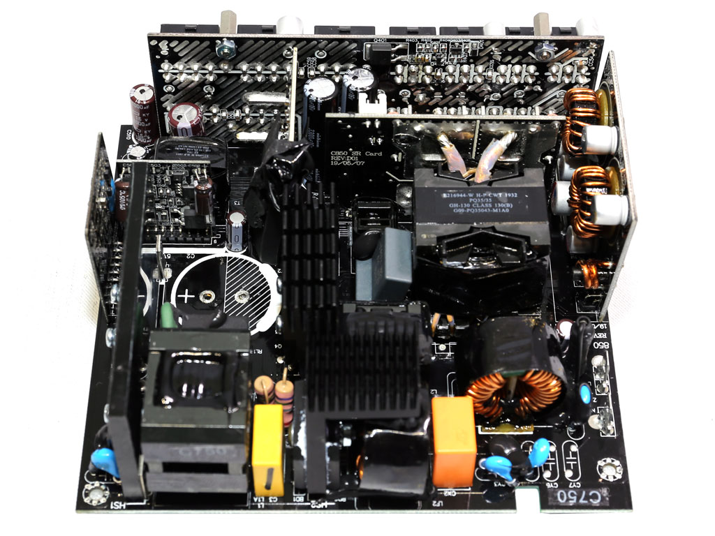
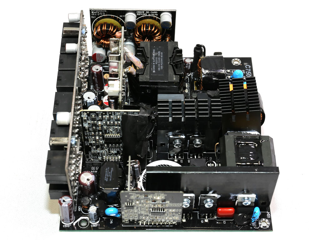

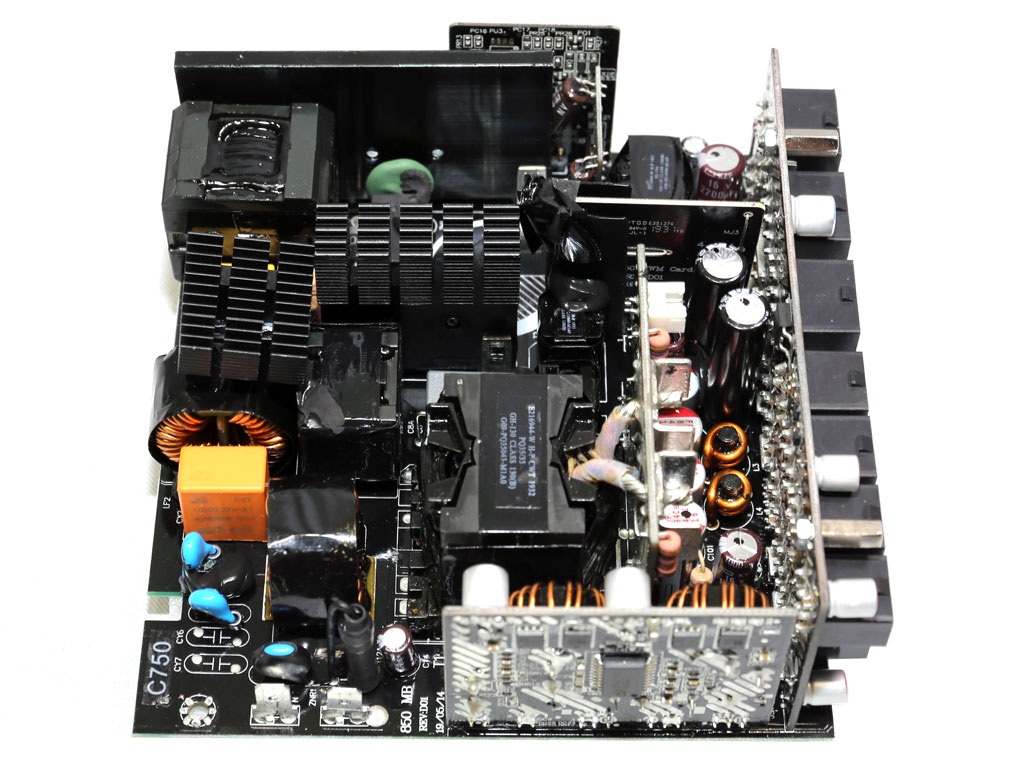
This is a new CWT platform with a very small PCB for its maximum power output. The design is clean as most power transfers are done through PCB traces instead of wires. However, such an overpopulated PCB doesn't allow for much space between components, so airflow won't be optimal. There are no proper heatsinks on the secondary side, which is typical for a CWT design, and the main transformer is connected to the +12 V board with a pair of short and thick wires. The +12 V board is right next to the main transformer to minimize energy losses and increase efficiency.

The transient filter has all the required components to suppress power surges and EMI emissions.

There is an NTC thermistor and bypass relay combo for restricting large inrush currents.


Each of the two bridge rectifiers can handle up to 15 A. They have been installed in parallel.


The APFC converter uses quality components, including a Chemi-Con cap rated at 420 V instead of the 400 V many manufacturers use to decrease cost.


The primary switching FETs are configured in a half-bridge topology. A resonant converter is also utilized to reduce energy losses.

The FETs that regulate the +12 V rail are installed on a vertical board right next to the main transformer. CWT uses a few small heatsinks to cool down these FETs.
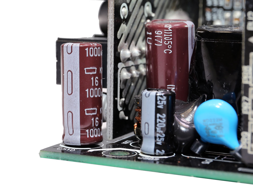

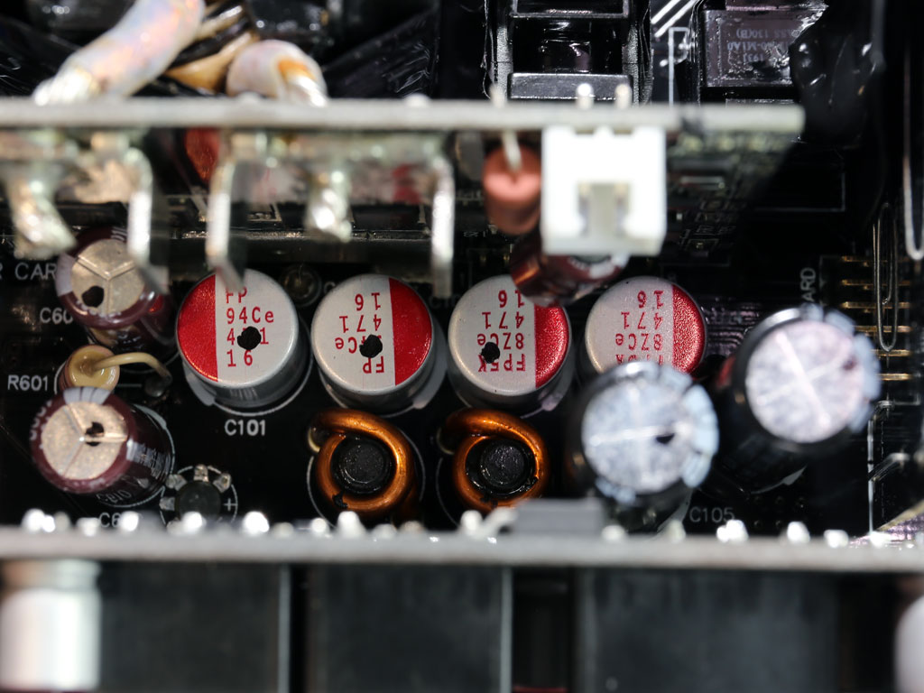
The majority of electrolytic caps are of very high quality. Many polymer caps are also used for ripple-filtering purposes.


Two voltage regulation modules generate the minor rails.

The 5VSB circuit uses a FET on its primary side and an SBR on its secondary side.

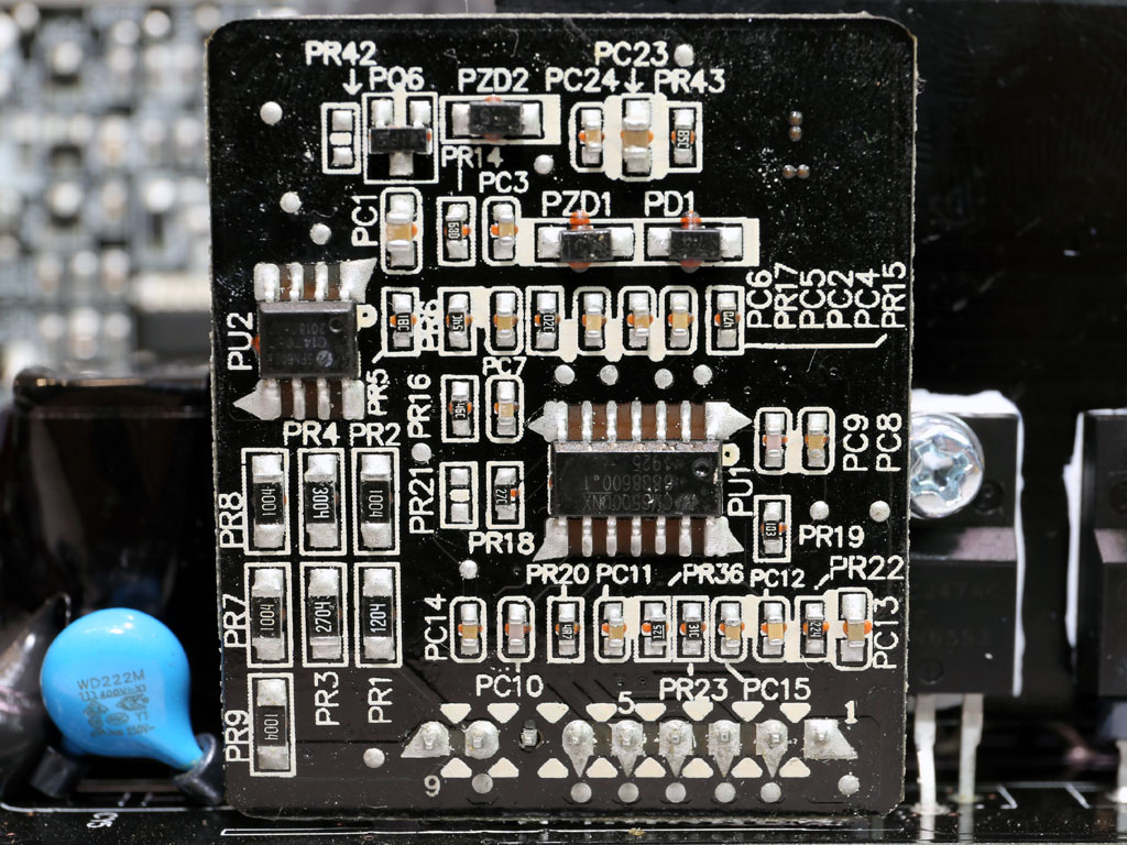
The supervisor IC is an IN1S313I-SAG.
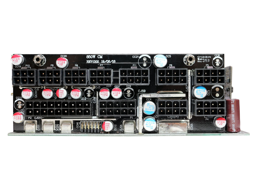


Lots of polymer caps are installed on the modular board as an extra ripple filtering stage.


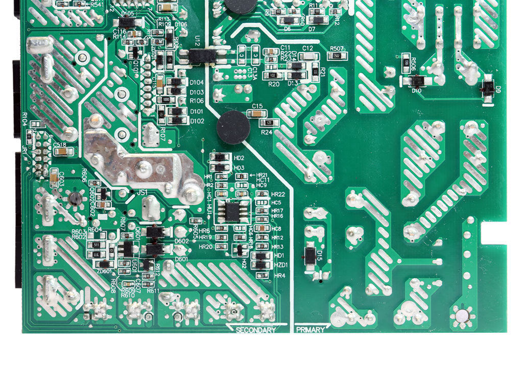
As per usual for CWT, soldering quality is good.
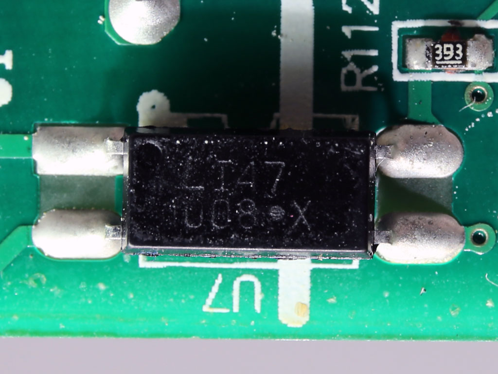
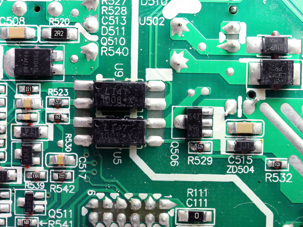


As is usually is the case, optocouplers are used to pass signals between the primary and secondary sides.

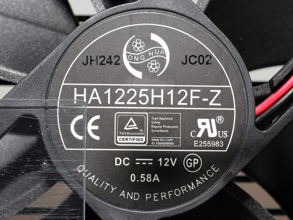
The cooling fan is provided by Hong Hua, a company that has managed to conquer the PSU manufacturing market with its fans. It uses a fluid dynamic bearing and measures 120 mm across.
Our Patreon Silver Supporters can read articles in single-page format.
Apr 24th, 2024 21:34 EDT
change timezone
Latest GPU Drivers
New Forum Posts
- (Anti) SFF fun house (347)
- Cinebench crashed my PC. My Wi-Fi stopped working, and I keep getting a "Please wait" screen when I boot up my PC. (30)
- The TPU UK Clubhouse (24783)
- Sharing experience with MSI RTX 3070 vBIOS update to enable Resizable Bar with MB Z490 (2)
- Share your AIDA 64 cache and memory benchmark here (2915)
- Will a RTX 4070 TI super bottleneck a Ryzen 9 7950X3D? (58)
- The best *budget* ATX PC case on the market? (24)
- GTX 1070 Ti - TDP Issues - Always Power Throttling (4)
- 2022-X58/1366 PIN Motherboards NVME M.2 SSD BIOS MOD Collection (656)
- Meta Horizon OS (15)
Popular Reviews
- Fractal Design Terra Review
- Thermalright Phantom Spirit 120 EVO Review
- Corsair 2000D Airflow Review
- Minisforum EliteMini UM780 XTX (AMD Ryzen 7 7840HS) Review
- ASUS GeForce RTX 4090 STRIX OC Review
- NVIDIA GeForce RTX 4090 Founders Edition Review - Impressive Performance
- ASUS GeForce RTX 4090 Matrix Platinum Review - The RTX 4090 Ti
- MSI GeForce RTX 4090 Suprim X Review
- MSI GeForce RTX 4090 Gaming X Trio Review
- Gigabyte GeForce RTX 4090 Gaming OC Review
Controversial News Posts
- Sony PlayStation 5 Pro Specifications Confirmed, Console Arrives Before Holidays (116)
- NVIDIA Points Intel Raptor Lake CPU Users to Get Help from Intel Amid System Instability Issues (106)
- AMD "Strix Halo" Zen 5 Mobile Processor Pictured: Chiplet-based, Uses 256-bit LPDDR5X (101)
- US Government Wants Nuclear Plants to Offload AI Data Center Expansion (98)
- Windows 10 Security Updates to Cost $61 After 2025, $427 by 2028 (84)
- Developers of Outpost Infinity Siege Recommend Underclocking i9-13900K and i9-14900K for Stability on Machines with RTX 4090 (84)
- TechPowerUp Hiring: Reviewers Wanted for Motherboards, Laptops, Gaming Handhelds and Prebuilt Desktops (78)
- AMD's RDNA 4 GPUs Could Stick with 18 Gbps GDDR6 Memory (73)