 0
0
Gigabyte Sumo Power Silver 900 W Review
Voltage Regulation & Efficiency »A Look Inside
Before reading this page we strongly suggest to take a look at this article, which will help you understand the internal components of a PSU much better.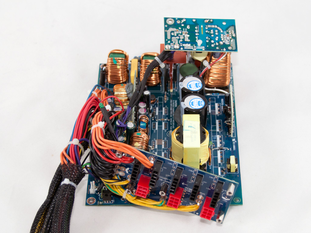

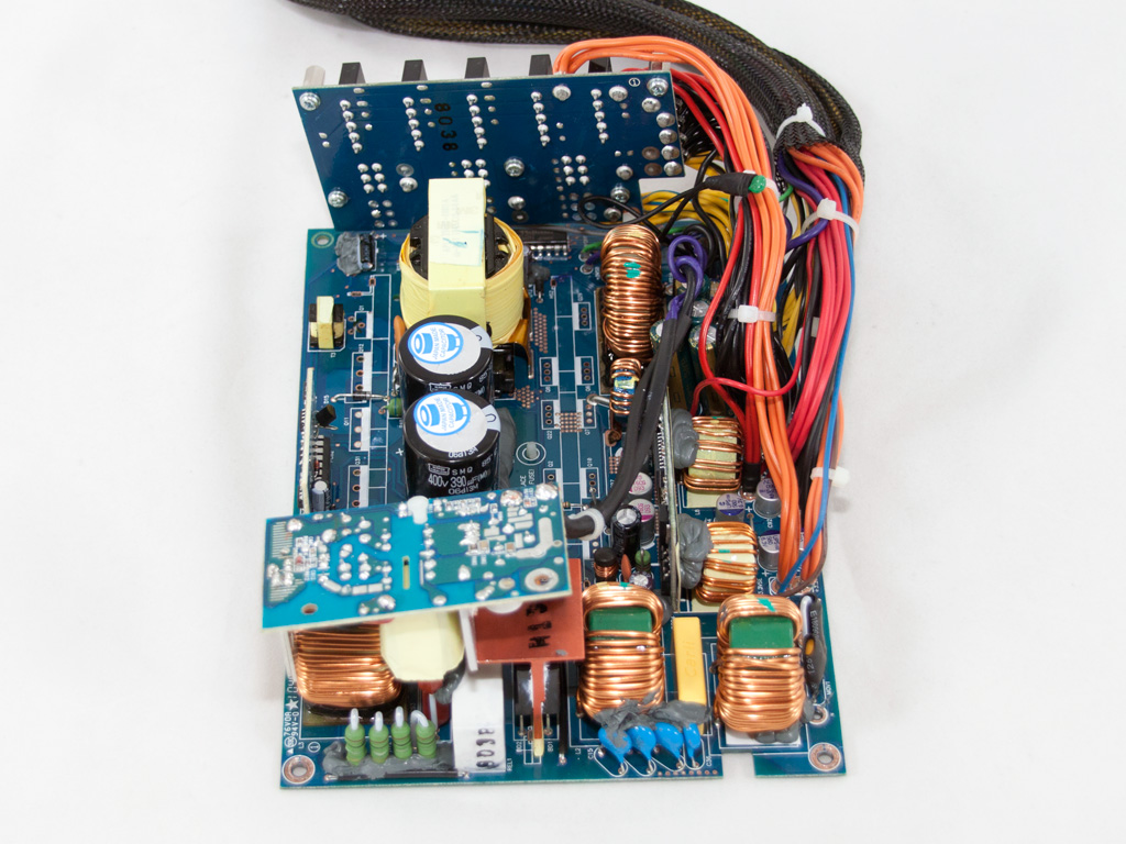


The OEM of this unit is Acbel Polytech, a manufacturer that we don't meet very often in our PSU reviews. The main PCB is huge and covers all the available internal space of the case. Also there is a smaller PCB on top of the main PCB which houses the 5VSB circuit. The platform, although it is merely 80 Plus Silver qualified, shares many components with platforms that achieve Gold efficiency; for example an electromagnetic relay to cut off the inrush protection thermistor once it finishes its job, DC-DC converters, solid capacitors in the secondary and the most important of all an Active Clamp Reset Forward (ACRF) topology which is also used in the Gold efficiency FSP Aurum units. To provide you with a better view we removed the APFC/primary and secondary heatsinks. Thankfully it wasn't too hard to do so (praise the Hakko 808 for this).
The transient filtering stage as usual starts right at the AC receptacle. In this unit we find one X and two Y caps there and the power wires are wrapped around a ferrite bead to suppress high-frequency signals. The transient filter continues on the main PCB with two CM chokes, four Y and one X caps and the necessary MOV (Metal Oxide Varistor).
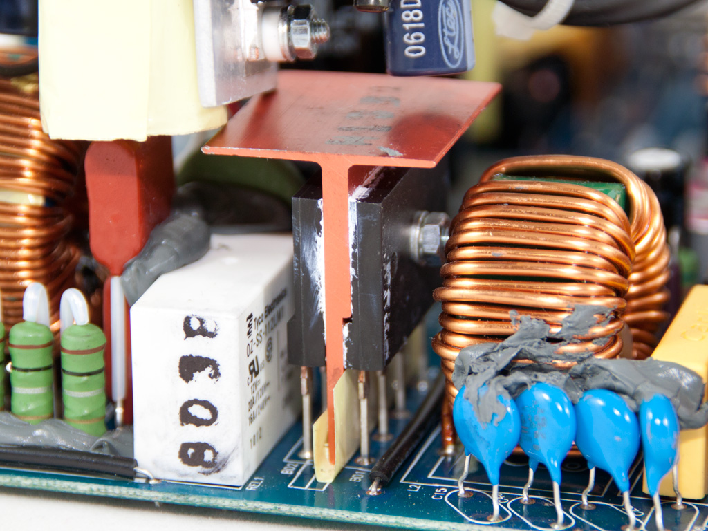
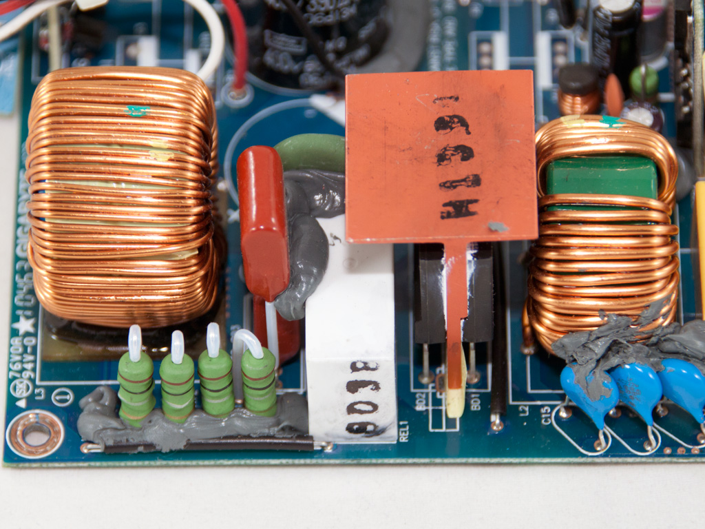
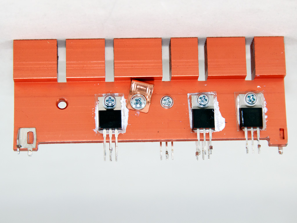
The two parallel rectify bridges (D15XB60) are provided by the Japanese company Shindengen and each one can handle up to 15A. A dedicated heatsink is used to cool them down. Right in front of the bridges we find the thermistor that provides inrush current protection and the electromagnetic relay which isolates it from the circuit, once its job is done, in order to reduce energy dissipation and allow it to cool down faster.


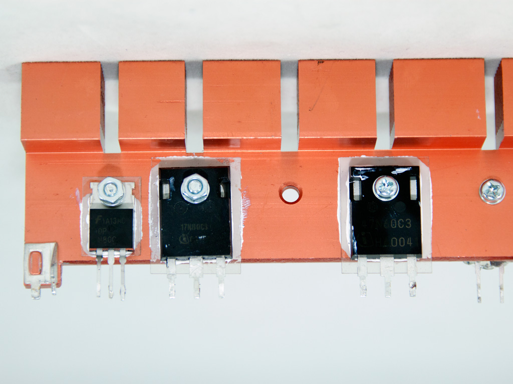

In the APFC only one mosfet is used, an SPW47N60C3, along with the necessary boost diode. As primary switches we find an SPW17N80C3 and an FQPF3N80C. The topology used, as we already mentioned at the start of this page, is called Active Clamp Reset Forward. Very briefly, in this topology two mosfets are used with one playing the role of the main switcher (Q1 - SPW47N60C3) while the other is the reset switch (Q2 - FQPF3N80C), which disconnects the APFC capacitors while Q1 is active. Also while Q2 is open, power is transferred from the primary to the secondary side. Obviously the main advantage of ACRF is the almost lossless switching of Q1, because while it is turned off the drain voltage is very low. This topology is mainly used by FSP in their Gold efficiency Aurum units. While it offers high efficiency its main problem is the high ripple at +12V rail (the lousy Cross Load performance in Aurums mostly have to do with their group regulation design in their secondary side rather the ACRF topology). Finally, we should note here that the FSP Aurum CM Gold 750W we have tested in the past uses almost the same mosfets as primary switches.


The two parallel hold up caps are provided by Nippon Chemi-Con (390μF, 400V, 85°C, SMQ series). We would like to see 105°C rated caps here but our main complaint is the low voltage rating, 400V, which is very close to the DC bus voltage (380VDC). The PCB in front of the APFC caps houses the combo PWM/PFC controller, the famous CM6800AG. The CM6800 in this case handles only PFC and the ACRF topology is handled by an NCP1562BG Active Clamp/Reset PWM controller which is located on the solder side of the main PCB.
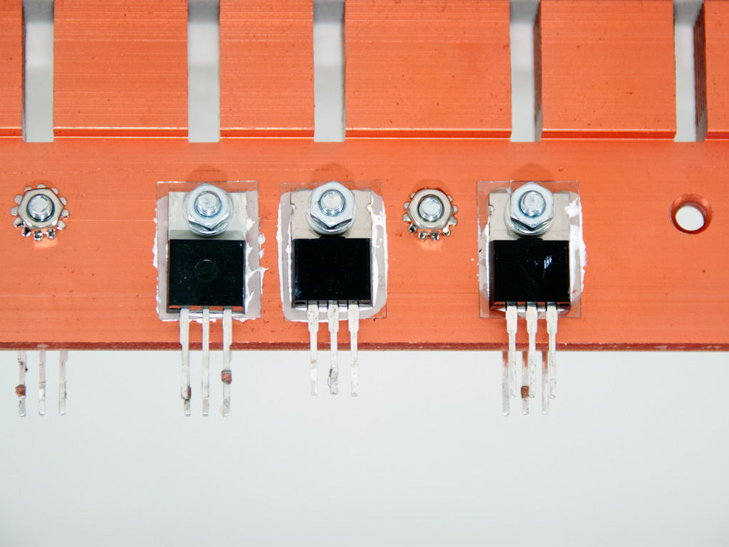


In the secondary synchronous design is used and the +12V rail is handled by three IPP037N08N3G and three IRF3205Z mosfets. The minor rails are generated by two DC-DC converters which are housed on the same PCB. The PWM controller of both VRMs (Voltage Regulation Modules) is an APW7159 and two pairs of M3006D and M3004D mosfets are used in each VRM. In the secondary side we find some polymer caps and several electrolytics which are provided by Teapo and Ltec. We would highly prefer all caps to be provided at least from Teapo since Japan made ones apparently would significantly increase cost.
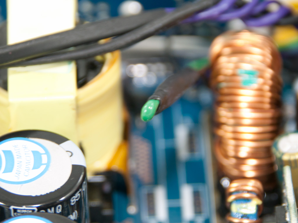
On the secondary heatsink we found this thermistor firmly attached.

Housekeeping duties are handled by a Weltrend WT7527 IC. This IC supports OCP only for two +12V channels so the OCP for the other three must be implemented through an alternative solution.

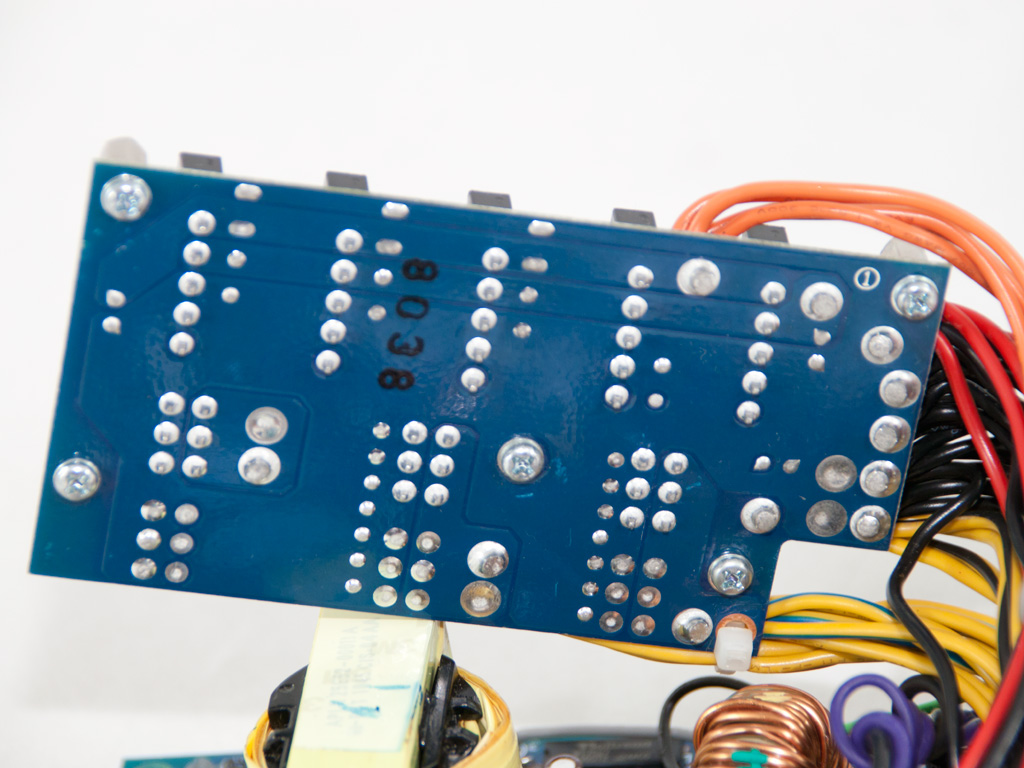
On the front of the modular PCB, although there are lots of vacant places, we didn't find any filtering caps. That's a shame because they would greatly help in ripple suppression. On the back of the modular PCB soldering quality is pretty good.


The main PCB enjoys high quality soldering jobs and a very clean design. We were amazed to see such high quality, which can be compared to Delta and Seasonic's implementations, from an OEM that is not so widely known.
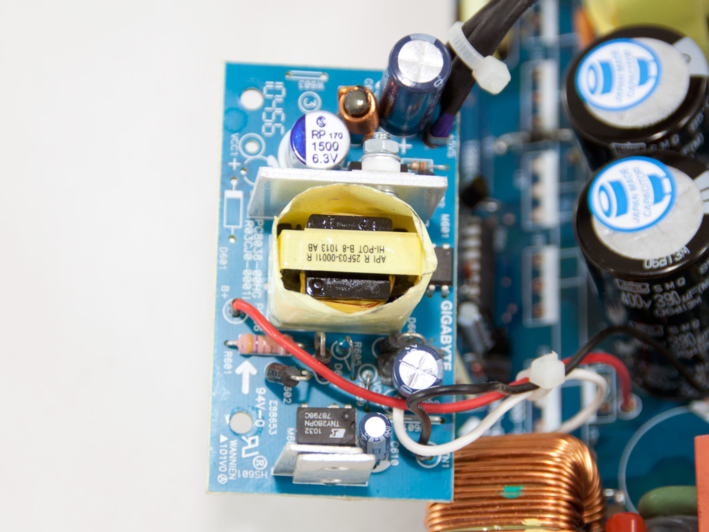
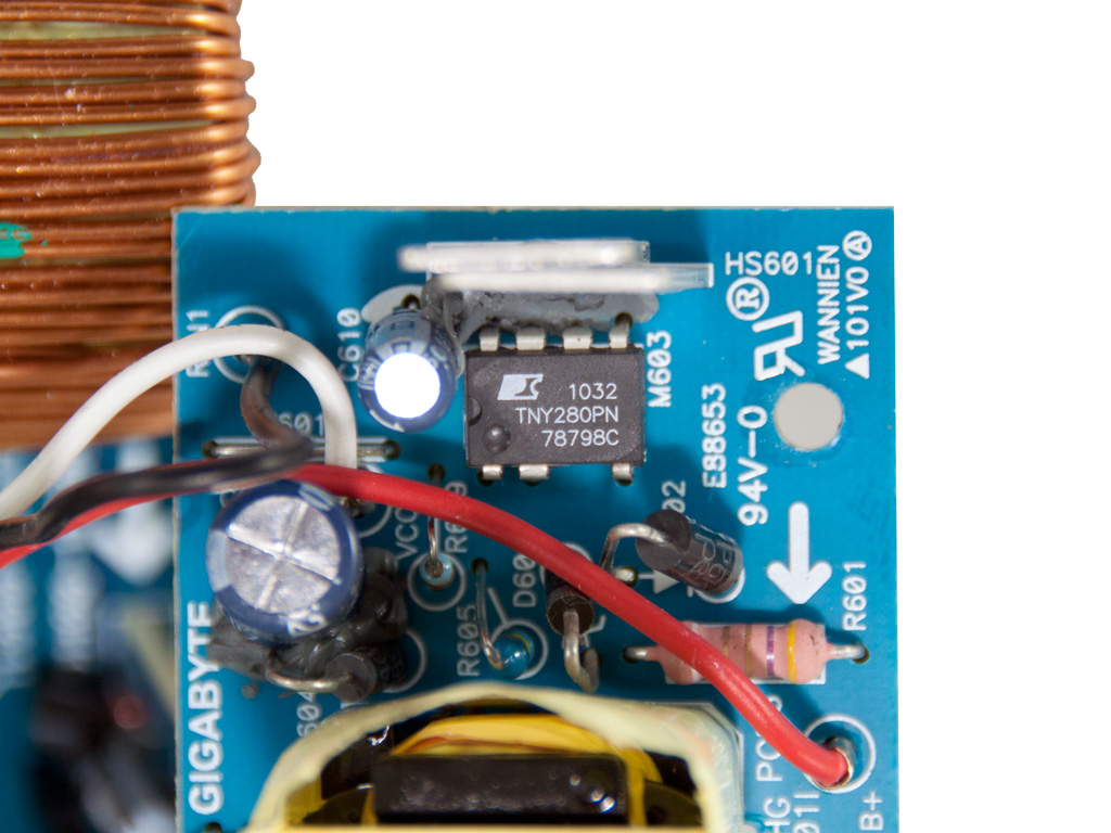
The 5VSB circuit is housed on a separate PCB. There we find a TNY280PN standby PWM controller and an SBR20A40CT. The latter can handle up to 20A current while 5VSB can deliver 4A max, talk about over-spec here!
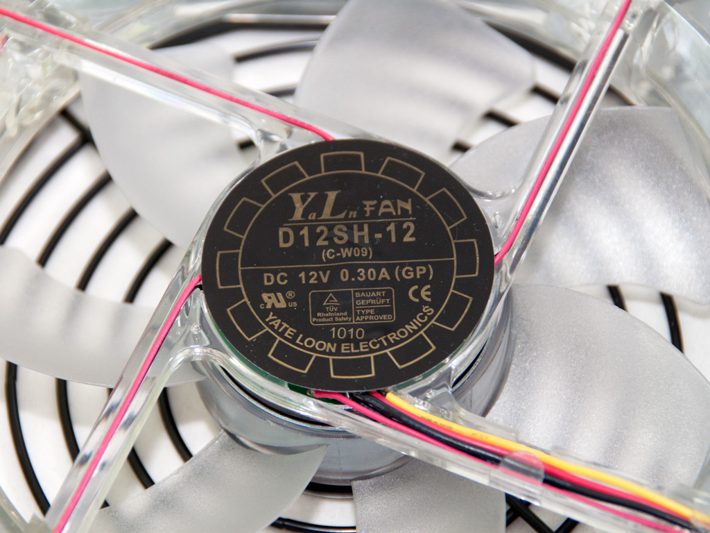
The cooling fan is provided by Yate Loon Electronics and its model number is D12SH-12 (12V, 2200 RPM, 88.0 CFM, 40 dBA). We can't help but wonder why they chose to use an 120mm fan while there was plenty of space for a similar performing, but significantly quieter, 140mm model. Instead of the LED lights we would highly prefer a larger, quieter and with ball bearings fan.
Apr 26th, 2024 20:24 EDT
change timezone
Latest GPU Drivers
New Forum Posts
- Strange system crashes out of nowhere help (9)
- What phone you use as your daily driver? And, a discussion of them. (1494)
- looking to build a new system and im considering asrock brand but i have some doubts/concerns. (12)
- Secure boot already open help (11)
- TechPowerUp Screenshot Thread (MASSIVE 56K WARNING) (4213)
- The Official Linux/Unix Desktop Screenshots Megathread (705)
- Alphacool CORE 1 CPU block - bulging with danger of splitting? (32)
- Your PC ATM (34508)
- Black screens leading to restarts (Event ID 18) on AMD platform since changing graphics card (42)
- Best SSD for system drive (104)
Popular Reviews
- Ugreen NASync DXP4800 Plus Review
- MOONDROP x Crinacle DUSK In-Ear Monitors Review - The Last 5%
- HYTE THICC Q60 240 mm AIO Review
- Thermalright Phantom Spirit 120 EVO Review
- Cougar GX-F Series 750W Review
- Corsair iCUE Link XC7 RGB Elite CPU Water Block Review
- CeBIT 2008: Cyber E Sport Review
- XFX Radeon RX 7600 XT Qick 309 Review
- Gigabyte GeForce RTX 3090 Eagle OC Review
- CeBIT 2008: Akasa Review
Controversial News Posts
- Windows 11 Now Officially Adware as Microsoft Embeds Ads in the Start Menu (135)
- Sony PlayStation 5 Pro Specifications Confirmed, Console Arrives Before Holidays (117)
- NVIDIA Points Intel Raptor Lake CPU Users to Get Help from Intel Amid System Instability Issues (106)
- AMD "Strix Halo" Zen 5 Mobile Processor Pictured: Chiplet-based, Uses 256-bit LPDDR5X (103)
- US Government Wants Nuclear Plants to Offload AI Data Center Expansion (98)
- AMD's RDNA 4 GPUs Could Stick with 18 Gbps GDDR6 Memory (95)
- Developers of Outpost Infinity Siege Recommend Underclocking i9-13900K and i9-14900K for Stability on Machines with RTX 4090 (85)
- Windows 10 Security Updates to Cost $61 After 2025, $427 by 2028 (84)