• Welcome to TechPowerUp Forums, Guest! Please check out our forum guidelines for info related to our community.
  • The forums have been upgraded with support for dark mode. By default it will follow the setting on your system/browser. You may override it by scrolling to the end of the page and clicking the gears icon.

mobo/case connection

Joined
Oct 28, 2011
Messages
111 (0.02/day)
Location
Pensacola, Fl
System Name Intel
Processor Intel core i5
Motherboard Intel DH57DD
Memory 2-2gb kingston DDR3-1333/PC-10600 SDRAM
Video Card(s) NVIDIA GeForce 9500 GT ( 1GB DDR 2 )
Storage Western Digital SATA/ 32MB Cache (WD52002AALX) 500gb
Case CM Storm - Scout Edition
Audio Device(s) unknown
Power Supply VisionTek 700W
Software Windows 7
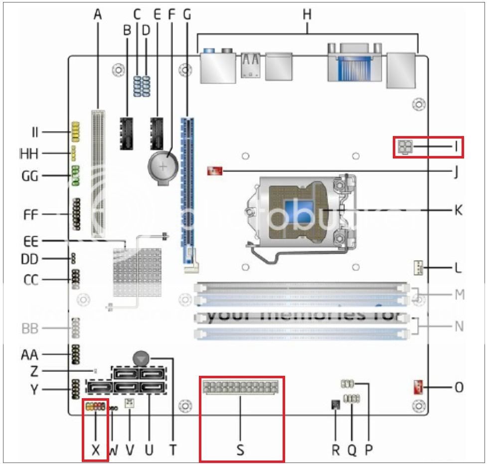
People this is my issue! I have a Intel DH57DD mobo ( link to mobo layout http://www.intel.com/support/mother...914.htm?wapkw=(Intel+Desktop+Board+DH57DD)and I have a CS Storm "Scout" case. My issue is getting the wires from the front of the case to connect to the right spots on the mobo.

I have been trying to connect these wires to the "front panel header" part of the mobo. The wires are as follows "power led + power led -" "power sw" "reset sw" and "hdd led". The wires run directly from the front of the case. Each wire has a pin sized hole hence the reason for putting them in the front panel header section.

The wire colors are blue/white, orange/white, red/white, and green in white. On the mobo in the front panel header section there are 2pins sections that are blue and side by side, so I tried putting the blue/white wires there... didn't work.

I am getting power to the mobo, the rest of my mobo is wired correctly. Guys, help please! I have tried all sorts of combos and am getting nowhere.

thanks in advance
 
CLICK HERE!
OR HERE!

That link tells you what goes where on that FP header, make sure you're getting the positive and negative ones in the right spots.

After you double check what's going where, and if it still doesn't work, then you may have pulled the connections out of the top of the case- not to worry, just push them back in, but on the scout, that requires some disasembly of the top part of the case.
 
still a no go on the mobo

Sinzia, thank you for the 411! however it did not work. I pulled the top off of the case as you suggested and everything is fine.
I know that my mobo is receiving power because the "standby" light is on. I have the SATA wire also running into the mobo as well. Is there a step that I am missing? I have spent several hours on this trying to figure it out. It will probably be something that was right in my face the whole time that I was missing-lol
 
24 pin power connector, 4/8 pin aux connector plugged in?
 
To be honest I do not know if my mobo has a 4/8 pin aux connector. The diagram that I posted in my first link I did not see listed on my mobo. Could the case just no be compatible w/ my mobo or the case itself is damaged. The fans and the fan lights for the case work but they are not connected to the mobo.
I may just taked the compute back apart and re-assemble it and if that doesn't work I will take the case back.
On the diagram that you sent for the section fp header does it matter which way the power sw goes on. For instance it goes on but if it doesn't work turn it around to the other way to make sure the +'s and -'s are correct. there is no + or - on the power sw, only for the led.
thanks Sanzia for your time on this
 
See if your reset button works for power. Connect the reset button pins to the reset sw header. Might just be the power switch is bad.
 
I do not any signs of life when the fw header wires are set on the mobo. the only signs of life that I see is the standby light is on and when I first turn on the power the fans and the fan lights run for about a 2 seconds and that is it.
so either I am missing something simple or it is the case, or mobo or whatever, I'm going nuckin futs over this. I have spent 3 days on this issue

so it is one of three things - its me, the mobo or a faulty case. I am a newb @ assembling a comp. from scratch but the wiring from the front of the case has seemed to be my only issue - that I know of.
would it be o.k. if I were to hook the wires from the front and then test the wires to see if the are receiving power? it would require a pin sized hole in the plastic of the wiring,
 
Last edited by a moderator:
so it is one of three things - its me, the mobo or a faulty case. I am a newb @ assembling a comp. from scratch but the wiring from the front of the case has seemed to be my only issue - that I know of.
would it be o.k. if I were to hook the wires from the front and then test the wires to see if the are receiving power? it would require a pin sized hole in the plastic of the wiring,

Rather than doing that, you can tell if the switches are functioning properly by testing with an ohmmeter.

Both power and reset switches are the momentary type. That is, they are only closed while you are pressing the switch.

Connect your ohmmeter to the leads at the connector and press the corresponding switch while observing your ohmmeter. The resistance should go from infinite (open circuit) to nearly 0 (dead short). (Some meters have a diode check function that will give an audible signal when continuity is present. Use that if your meter has it.)

This method will isolate the switches from the rest of the system. If both switches are operating properly, then you may move onto the next step of verifying motherboard operation.
 
@autigerfan,

You do have the connectors plugged into "I" and "S", correct?

DH57DDhighlighted.jpg


And you are using "X" for the front panel connectors, correct?
 
Last edited:
Here's a general rule of thumb. This isn't always the case but more often than not it is. Generally on the front panel wiring the white wires are almost always the negative. So if you have a reset button connection that is blue and white the blue wire should be positive.
 

Attachments

  • FP_Wiring.jpg
    FP_Wiring.jpg
    31.7 KB · Views: 12,421
Here's a general rule of thumb. This isn't always the case but more often than not it is. Generally on the front panel wiring the white wires are almost always the negative. So if you have a reset button connection that is blue and white the blue wire should be positive.

Unless it is a lighted switch, it really does not matter. Polarity is only an issue with the LEDs.

It is only a switch, it does not care about polarity. It simply makes a temporary connection.

When I am working on motherboards outside the chassis, I have a jumper cap that I took off the BIOS reset header on an old motherboard that I use to start or reset the system. I place the cap on the appropriate pins on the motherboard header for a second, and then remove it.
 
The processor core power "I", I do not have a cable for that. My II (audio cable) and the main power cable are in the right spots.

Could I have the wrong power supply? I double checked my wires and had my wife (who is a literal genius- she is a member of MENSA) and she did not see one either.
 
The processor core power "I", I do not have a cable for that. My II (audio cable) and the main power cable are in the right spots.

Could I have the wrong power supply? I double checked my wires and had my wife (who is a literal genius- she is a member of MENSA) and she did not see one either.

What is your PSU?

I believe the fact you do not have the CPU power connector "I" plugged in may be your problem.
 
I just checked the side of my power supply box,,,the "connector table of contents" is the following' 20+4 main connector ; 4+4 e ps 12v connector; 6 pin PCIe connector; 6+2 pin PCIe connector; 4pin peripheral connector; sata connector; floppy connector. It also had a picture of each of the connectors and there is not one that would fit into the processor core connector 2x2.

the back of my psu lists under the "support" is the following:
slide in 20+4pin for mobo
4+4 for cpu
PCIe 6+2 connector for VGA
 
Last edited by a moderator:
The 4+4 EPS is the one you want.

You should be able to insert it, with one-half of the connector in the motherboard receptacle, and the other half overhanging out of the receptacle. It is keyed to only go in one way, so do not try to force it.

Anyway, what is the brand/model of your PSU?

@autigerfan,

For reference, here is a pictorial of the various PSU connectors:

http://www.playtool.com/pages/psuconnectors/connectors.html
 
Last edited by a moderator:
ok. ok, good news/bad news. I was able to split on of the cables and I have the power cordfor the cpu plugged in. now here is the bad news. I have all of the cables/wires in the right spot for the front of the case and nothing! when the cpu power cable was out the fans would run for a brief second and the lights for the fan would light up. now that I have the cpu power plugged in, the fans don't turn on at all for the cpu and the same problem still exists the power will not turn on from the front of the computer.
On the fw header area should there be a wire for the +5v because I do not have one
 
OK, you have done the continuity check on the switches, correct?

You might try resetting the BIOS by turning off and unplugging the PSU and removing the battery "F" for a couple of minutes.

My apologies, I was looking at he wrong diagram of your motherboard, you should be connecting to "X" not "II". It has been a long day and I am tired, also trying to do other things at the same time.

I am editing my other post.
 
Last edited:
i do not know how to do a "continuity check
 
i do not know how to do a "continuity check

Do you have an ohmmeter/multimeter?

Also, see my previous post, I mistakenly told you the wrong header to use.
 
no worries about making the mistake these things happen. I appreciate the fact that you are attempting to help. I have all of the wires from the front of the case in the right spot. I have checked, double checked and then even had my wife take a look at it comparing the diagram and the wires to see if i had them in place correctly which i did.
I would remove the battery but i do not know enough about it and would not want to break it. I have the main power from the psu to motherboard in.. the power to the cpu,,2x2. i have the 8 pins filled up on the fwheader. (only one pin is empty and that is the +5v and i don't see a wire for that). usb cord from the front of the of the case to the mobo. the II connected,, 3 sata cables running into the mobo ( the main one for the mobo, dvd and hard drive).
is there anything that i am missing? i have power cable running to the dvd and hard drives but those should not have an issue on wether or not the power switch from the front of the case works or not.
 
OK, at this point I would concentrate on getting the motherboard to start.

Let us do this;

Unplug everything except the CPU power connector, 24-pin connector, and the front panel switches. Of course, leave the RAM and video card (if you have one) installed. Just unplug the various cables.

If successful, the CPU fan should start and the speaker should beep once.

Looking at this diagram:

http://www.intel.com/support/motherboards/desktop/sb/CS-009016.htm

The +5V is an output, so I would not worry about it.
 
Last edited:
will give it a try.
 
I take it you do not have a meter to check the switches, then?

If it does not start with the front panel switch, you can take that set of wires off the header and use a small screwdriver to touch the two pins (#6 and #8) for a second or two to see if it comes on.

Be careful and leave the LED connections on the header so you do not accidentally touch them.

Regarding removing the battery, it is very easy. For safety, unplug your PSU first.

See this YouTube video:

http://www.youtube.com/watch?v=tkBWZOtp2is
 
Last edited by a moderator:
Not to butt in on ya'll, but when, autigerfan states,
I was able to split on of the cables and I have the power cord for the cpu plugged in.
Some PSUs have a 20+4 connector... did he/she split this and plug in the 20 pin connector into S and take the 4 pin connector and plug it into I ?:confused:

There should be a separate 4 pin, 4+4 pin, 8 pin or some such configuration, plus the 20+4 or 24 pin one.

What make and model of the PSU?
It would probably help if you (autigerfan) filled out your System Specs in the User CP section and click on the show box.:)
 
Not to butt in on ya'll, but when, autigerfan states,Some PSUs have a 20+4 connector... did he/she split this and plug in the 20 pin connector into S and take the 4 pin connector and plug it into I ?:confused:

There should be a separate 4 pin, 4+4 pin, 8 pin or some such configuration, plus the 20+4 or 24 pin one.

What make and model of the PSU?
It would probably help if you (autigerfan) filled out your System Specs in the User CP section and click on the show box.:)

I am hoping it was the 4+4 EPS he split.

I would have to check, but I believe the 4-pin on the 20+4 ATX connector is keyed differently, and cannot be inserted into the CPU power receptacle.

I also was hoping he would have answered about the PSU brand/model.
 
Back
Top