 10
Sandisk DC SN861 7.68 TB Review
NVMe Power States »Teardown
Upon opening the SSD, we see that it's secured with four Phillips T-6 screws. Once removed, the back side of the PCB is revealed, firmly attached to the metal housing via several thermal pads that help dissipate heat from key components.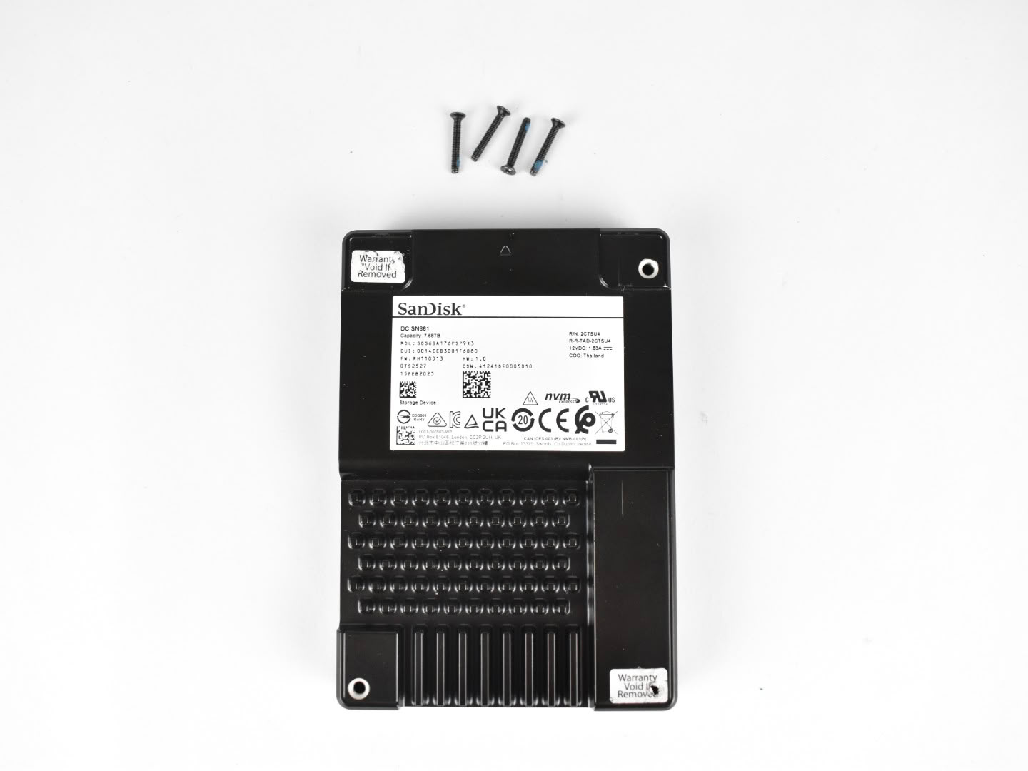
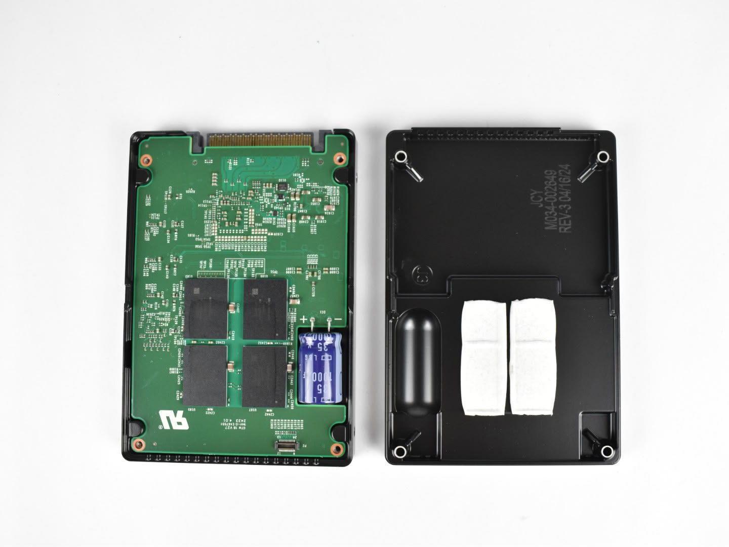
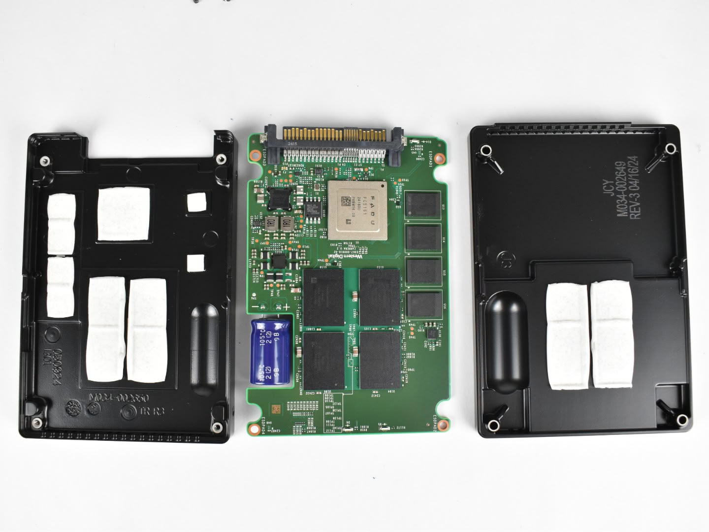
After removing all four screws, after removing the four screws securing the enclosure, we gain access to the SSD's internal PCB. The rear side houses four NAND flash packages, while removing the PCB from the metal chassis reveals the front side, which contains the drive's primary components. Here we find the FADU FC5161 controller, which we'll discuss in more detail below, along with four additional NAND flash packages, four DRAM cache ICs, and the supporting circuitry for both the VRM and the Power Loss Protection (PLP) system.
Controller

This SSD features the FADU FC5161, an in-house developed enterprise controller from the South Korean company FADU. It is a 16-channel controller designed for PCIe 5.0 SSDs and manufactured on an advanced process node. The controller adopts a heterogeneous RISC-V architecture, combining SiFive Essential 64-bit S51-MC application cores with 32-bit E31-MC microcontroller cores, both featuring floating-point units (FPUs). This design allows compute-intensive storage tasks to be separated from lower-level system management functions, improving efficiency while maintaining the flexibility offered by the open-standard RISC-V ISA.
Its 16 NAND channels communicate with the flash memory at speeds of up to 2400 MT/s, a significant increase over previous-generation enterprise controllers. The FC5161 also supports PCIe 5.0 x4, NVMe 2.0, and Flexible Data Placement (FDP), along with support for up to 128 namespaces, making it well suited for hyperscale and cloud storage deployments.
Similar to other modern enterprise controllers, FADU's adoption of the RISC-V architecture reflects the growing industry trend toward open-standard processor designs. Compared to traditional Arm-based solutions, RISC-V offers greater flexibility for architectural customization, allowing vendors to optimize their controllers for specific workloads while maintaining high performance, power efficiency, and low-latency operation.
DRAM Cache
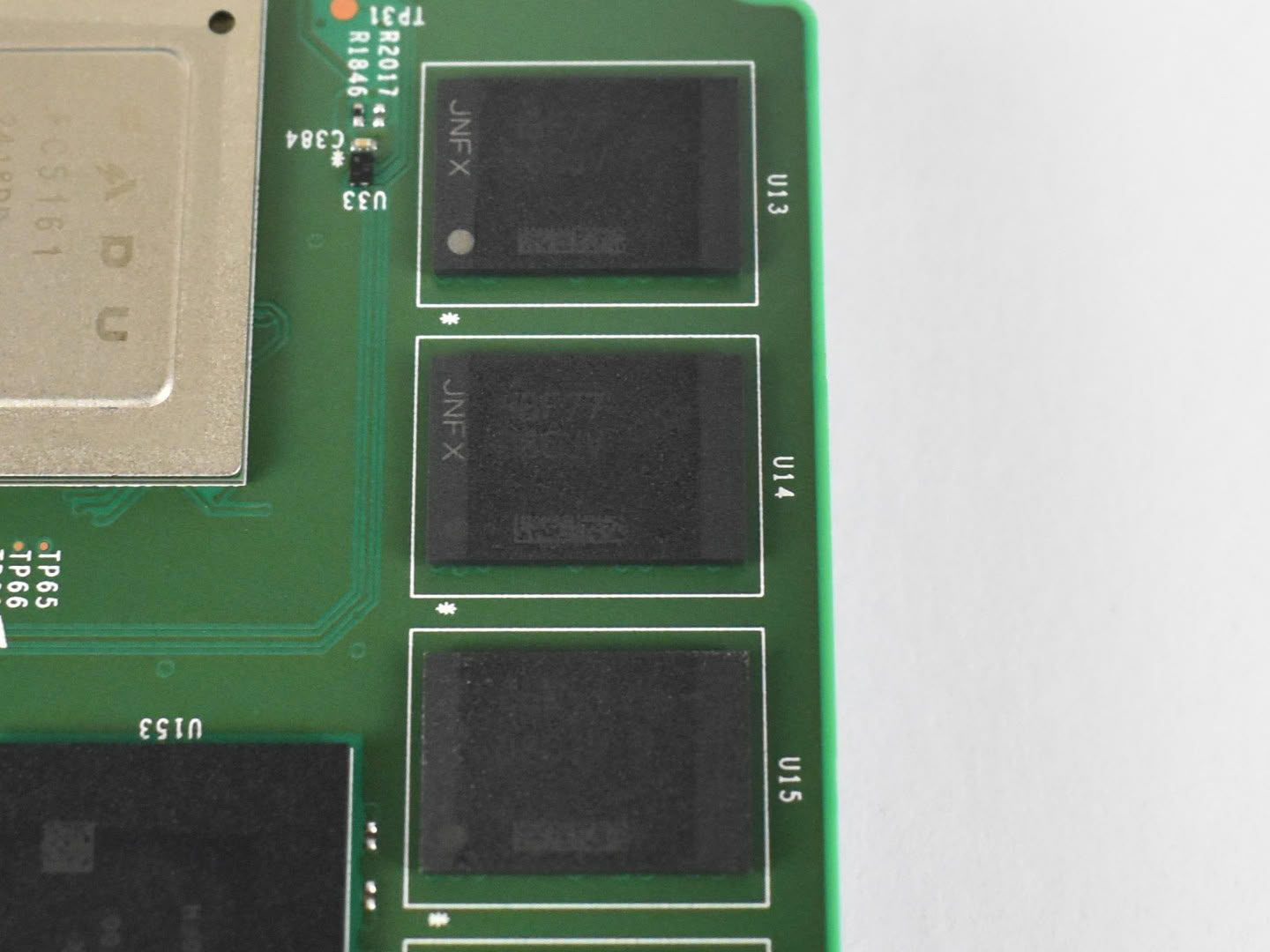
The SSD comes equipped with a total of four DDR4 chips from the North American manufacturer Micron, with 4 modules on the front side of the PCB. The specific model used is the D8CJV, using Micron's own decoder we get the MT40A2G8SA-062E:F (F-Die) which is a 16 Gb module (2 GB) supporting a bandwidth of up to 3200 MT/s CL-22, with a total of 8 GB of DRAM Cache.
NAND Flash
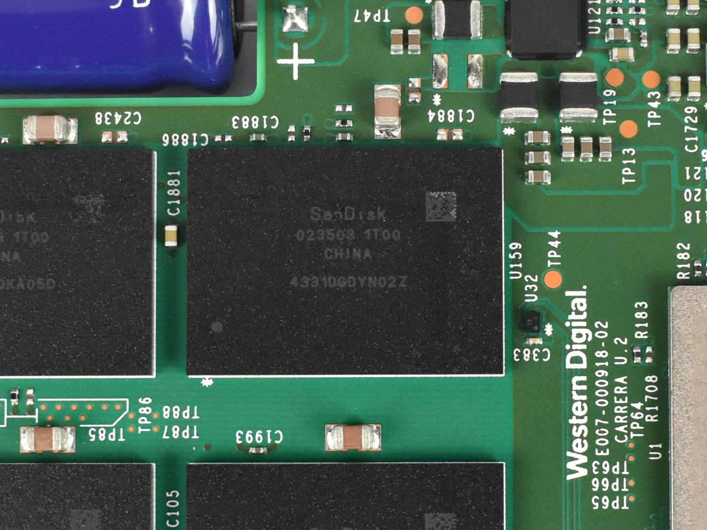
Our SSD features a total of eight NAND packages, with four placed on each side of the PCB. The NAND used in this design is manufactured by Sandisk, specifically the Kioxia/Sandisk BiCS6 512 Gbit TLC 162-layer (FXZ5 512G) dies.
Each NAND die has a capacity of 64 GB, and with a total capacity of 8 TB, each package provides 1 TB, meaning that each NAND package contains 16 dies internally. The NAND is marked as 023503 1T00 4331DGD, and each die measures approximately 49 mm², resulting in a storage density of around 10.4 Gb/mm², an impressive figure for this generation, newer dies from Sandisk and Kioxia themselves have greatly increased their efficiency and storage density.
These dies are capable of interfacing with the controller at speeds of up to 2400 MT/s, although actual performance depends on the controller's capabilities. Thanks to its 16-channel architecture, it has more than enough bandwidth to comfortably saturate a PCIe 5.0 x4 interface.
Structurally, these NANDs use two decks of 81 active storage layers combined with 22 dummy wordline layers alongside a 4-plane design alongside other supporting structures. Altogether, this achieves an array efficiency of over 88.4%. Higher array efficiency means less silicon area is wasted, improving cost-effectiveness and potentially delivering better performance relative to die size.
VRM - Power Circuitry
Just like any other electronic component we use in our daily lives, SSDs require power in order to operate. Graphics cards, processors, and motherboards all have voltage regulators to supply power to their respective circuits—and the power delivery for SSDs works in the same way. In the next section of our analysis we'll take a closer look at these details.
The primary power management IC is the Qorvo ACT85411, a highly integrated PMIC specifically designed for enterprise SSDs. It combines multiple high-efficiency switching regulators, including dual synchronous buck converters, a buck-boost converter, and an LDO regulator, while supporting an input voltage range of 2.7 V to 14.4 V. The IC also integrates programmable eFuse protection, capacitor health monitoring, and dedicated Power Loss Protection (PLP) management.
Beyond supplying stable voltage rails for the controller, DRAM, and NAND flash, the ACT85411 continuously monitors the backup capacitor and automatically switches the SSD to its stored energy during an unexpected power failure. By integrating voltage regulation, protection circuitry, and PLP control into a single device, it improves overall power efficiency while ensuring reliable operation and data integrity in enterprise environments.

This IC, marked MX25U12832F, is a 128 Mb (16 MB) SPI NOR Flash memory from Macronix. It stores the SSD's bootloader and initialization firmware, allowing the controller to start during power-on. Unlike the NAND flash, it does not contain user data or the Flash Translation Layer (FTL).
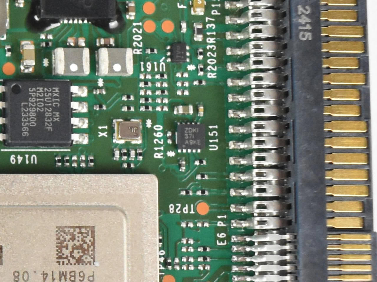
The IC labeled as ZDKI also known as TPS22954DSQR from Texas Instruments is a 5 A load switch featuring an ultra-low 14 mΩ ON resistance, programmable slew-rate control, power-good monitoring, and undervoltage lockout (UVLO). It also integrates quick output discharge and thermal shutdown protection, making it well suited for power sequencing applications in high-performance systems.
Within the SSD, this IC is responsible for enabling and disabling specific power rails while limiting inrush current during startup. Its controlled power sequencing helps reduce electrical stress on sensitive components such as the controller, DRAM, and NAND flash, contributing to the overall stability and reliability of the drive.
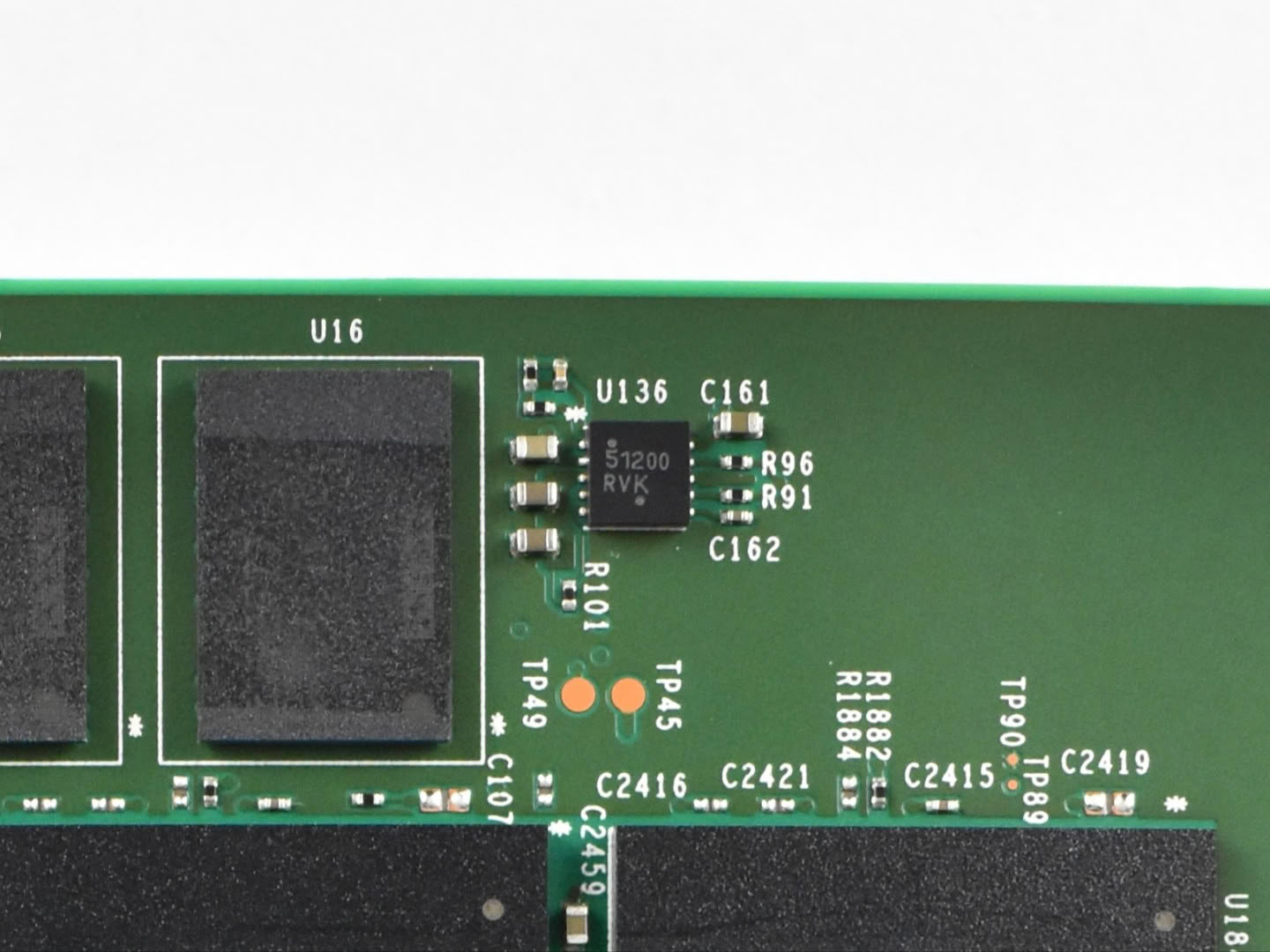
The IC marked 51200 is the ON Semiconductor NCP51200, a DDR memory termination regulator designed for DDR memory subsystems. It provides a stable termination voltage for the onboard DRAM cache while integrating protection features such as overcurrent, undervoltage, and thermal shutdown, helping ensure reliable operation under heavy workloads.
Power Loss Protection
Power loss protection in datacenter SSDs is essential to ensure data integrity during power failures. Using capacitors for temporary energy storage allows the safe completion of ongoing operations, preventing data corruption in critical environments. This ensures high availability and reliability of data.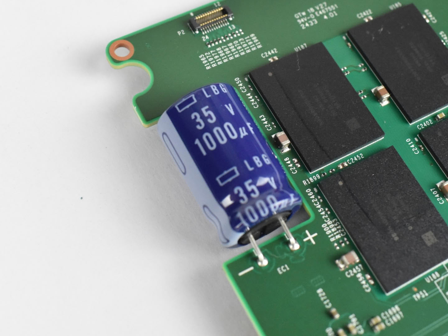
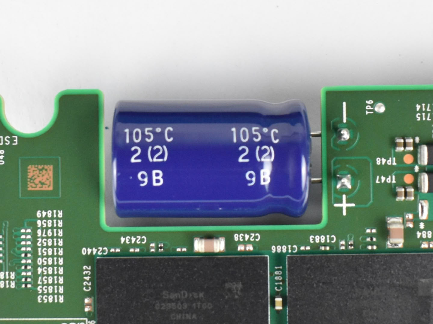
This SSD incorporates one aluminium electrolytic capacitor manufactured by Chemi-con. That capacitor operates at a voltage of 35 V with a capacitance of 1000 µF, and is rated to withstand temperatures of up to 105°C.
Estimated Hold Up Time
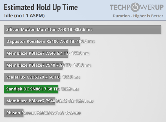
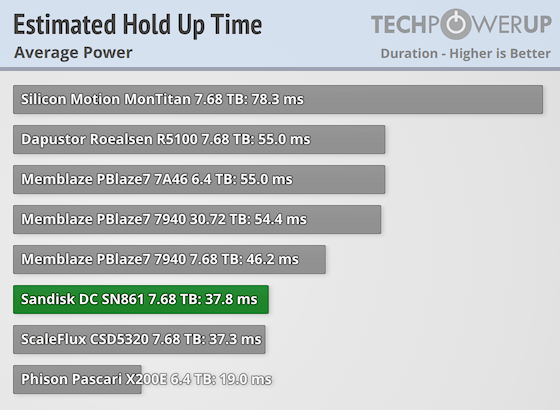
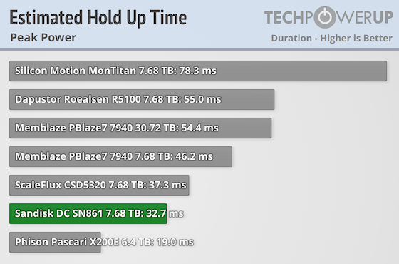
To estimate the hold-up time, we applied a set of equations that help approximate how long the drive can remain operational during an unexpected shutdown, based on its energy requirements. Our calculations use measured values for idle, average, and peak consumption. The analysis also considers the number and size of onboard capacitors, along with specific energy usage under various workload conditions.Please note: It's important to note that it's not an exact measurement, but rather a simplified calculation to illustrate how long an SSD might remain powered during a sudden power loss. In real-world conditions, power consumption is typically lower than the scenario shown here, which would result in a longer hold-up time.
Nov 15th, 2026 18:58 CST
change timezone
Latest GPU Drivers
New Forum Posts
- Can you guess Which game it is? (320)
- Your PC ATM (36431)
- It’s been fascinating times in Retro agian r36s isn’t even worth 50-65 dollars no more and newly listed Rm36 64gb 4in IPS models for only 34 dollars. (3)
- What is the latest game you finished or 100% (203)
- HP Office Jet 7740 Pro - Supply system problem with replacement cartridge (4)
- What are you playing? (26224)
- WarpCoreBench scores! (55)
- Local LLM General Discussion (691)
- Folding Pie and Milestones!! (10205)
- Asus Rog Maximus Z890 Extreme. (Various questions). (25)
Popular Reviews
- ASUS ROG Strix B850-I Gaming Wi-Fi7 W Review
- Corsair HX1000i Shift Crystal Review
- AMD Zen 6 Technical Deep Dive
- Upcoming Hardware Launches 2027 (Updated Nov 2026)
- Montech King 95 3D PRO Review
- NZXT C1200 Platinum Review
- Phantom Blade Zero Performance Benchmark Review - 35 GPUs Tested
- AMD Ryzen 7 9800X3D Review - The Best Gaming Processor
- NZXT H7 RGB+ Review
- NZXT H5 Review
TPU on YouTube
Controversial News Posts
- NVIDIA Co-Founder and CEO Jensen Huang Officially Resigns (430)
- Open Letter Asking NVIDIA to Reinstate Jensen Huang Passes 115,000 Signatures (184)
- OpenAI CEO Argues Home PCs Waste the World's Limited DRAM Supply (152)
- NVIDIA Launches Investigation Into Jensen Huang's Relationship With Suspected Chinese Spy (136)
- Intel "Raptor Lake Next" 16-Core and 20-Core CPUs Surface (130)
- Legendary Game Studio BioWare Shuts Down Following EA Layoffs (104)
- Dell CEO Says the Memory Shortage Will Get Worse in 2027 (95)
- NVIDIA GeForce RTX 50-Series Scheduled for up to $500 Price Hike This Week (89)