Sunday, November 30th 2025

BTF Connector Mod by Der8auer Makes ASUS Matrix RTX 5090 Pull 750W off 12V-2x6
There are software BIOS mods, such as the ASUS XOC BIOS that relaxes software-level power limits, letting ASUS RTX 5090 cards pull "up to 2000 W" of power; and then there are hardware mods, using power shunts directly on the card, which bypass hardware-level power limits. Der8auer discovered something in the middle for the ROG Matrix RTX 5090. This card has two ways you can power it—a conventional 12V-2x6 power connector on the top, and a detachable BTF (GC-HPWR) gold-finger that lets you pair the card with ASUS BTF motherboards that have a power delivery slot along the PEG x16 slot. ASUS made the BTF gold finger on the ROG Matrix RTX 5090 detachable so you can use the card on regular, non-BTF motherboards.
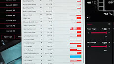
Der8auer learned that by shorting a few sense pins in the BTF gold finger while the card is connected to a 12V-2x6 power source raises the power limit drawn from the connector to 750 W, a 150 W increase over the 600 W (continuous) design limit of the connector. This 750 W isn't exactly an "excursion," because the increased power draw isn't happening within the power spike intervals defined in the PCIe 5.1 CEM specification, but rather, lengthier periods of continuous power draw above 600 W. There are, of course, a couple of catches. You'll need a PSU with fairly high power output and +12 V rail(s) connected to the 12V-2x6, a durable connector, and because the BTF gold finger is being modified, not only is the power source a 12V-2x6 connector, but also the card isn't directly slotted into the PCI-Express x16 slot, rather a PCIe Gen 5-capable riser cable is needed. At this point we don't know if the mod works with other ASUS RTX 5090 BTF cards, such as the ROG Astral RTX 5090 BTF.


Sources:
Der8auer (YouTube), VideoCardz
Der8auer learned that by shorting a few sense pins in the BTF gold finger while the card is connected to a 12V-2x6 power source raises the power limit drawn from the connector to 750 W, a 150 W increase over the 600 W (continuous) design limit of the connector. This 750 W isn't exactly an "excursion," because the increased power draw isn't happening within the power spike intervals defined in the PCIe 5.1 CEM specification, but rather, lengthier periods of continuous power draw above 600 W. There are, of course, a couple of catches. You'll need a PSU with fairly high power output and +12 V rail(s) connected to the 12V-2x6, a durable connector, and because the BTF gold finger is being modified, not only is the power source a 12V-2x6 connector, but also the card isn't directly slotted into the PCI-Express x16 slot, rather a PCIe Gen 5-capable riser cable is needed. At this point we don't know if the mod works with other ASUS RTX 5090 BTF cards, such as the ROG Astral RTX 5090 BTF.


16 Comments on BTF Connector Mod by Der8auer Makes ASUS Matrix RTX 5090 Pull 750W off 12V-2x6
well done.
Selling products which gives you the wrong impression of safety by only watching certain direct current flows over the 12Vxxx connector in certain ranges.
Thermal grizzly = the 8auer alias Roman H.
-- Something does not fit in the hole picture. When it works with 750W I may suggest a burn in period of 3 hours per connector with 1250 Watts each. When it did not burn to crisp it may be safer. Who knows?
How is the article misleading? Did debaur not mod the card?
I dont know what more you want.
Sure, it's a mod and says so in the text, but the circuitry on the cards in conjunction with the known issues of the 12VHPWR is just asking for brigged hardware, should it be used for more than testing.
If not for anything else, but the educational value of the information.
max current by specs is 8,5A, so with 6x 12V terminals max load is 612W
for comparasion old style connectors 6/8/24pin etc were mini fit 4.2 - each terminal max current 13A - so 6pin pci-e electrically (3x12V) 39A = 468W - 8pin has also 3x 12V so the same thing - so gpus with 3x8pin - 1300W :D
if you really need pushing 700-800W from card probably solder some wires directly to BTF slot will help to decrease current on 12vhpwr
First, the manufacturer (of all parts!) is not necessarily Molex. We need to save some money somewhere, right?
Second, there is current derating, meaning that the maximum allowed current decreases as a function of several factors. Some important details can be found in this document.
8.5 A is for a 2-pin, wire-to-board connection. We should be looking at 12-pin (12-circuit) data - the current is only 5.5 A here, and the reason is concentration of heat.
There's further derating above 74°C (tin-plated contacts) or 94°C (gold-plated contacts) - page 9.
Safety agencies have their own criteria and therefore their own ratings. Note that this is for the plastic shells (43020 etc), not the pins:
Third, there's always some imbalance unless currents are electronically balanced, which they aren't. They are somewhat balanced by wire resistance (15 mΩ for 70 cm of 18 AWG wire) and by small resistors on the PCB if they are there. The allowed contact resistance is 10 mΩ plus another 20 mΩ due to: mating cycles, vibration, shock, fretting corrosion (thermal cycling), thermal aging, and humidity (pages 12 through 15). A safety factor of 0.8 - 0.9 would probably be in order, meaning that 5.5 A shrinks to 5 A or so, and even that may be too optimistic.
thanks for additional information regarding this issue. ❤️🔥
still old 4,2 is better bcoz more spacing and even thicker wires avaible to crimp, I make custom cables and most of them on 1mm^2 wires (so little more than awg18, even 1,5mm^2 is possible to crimp on old style connectors - I tried with new 12vhpwr and special awg18 is max (with thinner insulation) on "crimping" shop they told me they can do max 0,5mm^2 on these
There's a very interesting discussion among people knowledgeable in electronics over at EEVblog. No wonder that they took note of this new connector with "special features". There are also graphs of contact resistance vs. number of mating cycles:
www.eevblog.com/forum/general-computing/atx-3-0-12vhpwr-connector-type-concerns/msg5818223/#msg5818223
www.eevblog.com/forum/dodgy-technology/nvidia-5090-connectorpower-cable-melting-again/msg5818157/#msg5818157Thinner wires will actually distribute the current more evenly, provided they are all of equal length and cross-section of course.