Sunday, September 13th 2026

ASRock's TempGuard Failed to Stop a PSU-Side Connector Meltdown on a $15,000 RTX PRO 6000 Rig

A repair shop technician has reported another melted 16-pin power connector on an ASRock Taichi TC-1650T PSU, paired with a $15,000 NVIDIA RTX PRO 6000 Blackwell Workstation Edition GPU. The former ships with native 12V-2x6 cables carrying ASRock's own NTC temperature sensor. According to the technician's Reddit post, the connector failed catastrophically on the PSU side and melted into the socket itself, even though both ends of the cable were fully seated. The GPU reportedly survived, and the damage was confined to the power supply side. The technician also says the sensor is mounted on the wrong side of the cable, on the ground line rather than the 12 V side it's supposed to watch, which would explain why it apparently never caught the rising heat in time.

ASRock added the NTC sensor and TempGuard system to its 12V-2x6 cables specifically to shut a system down before a connector melts. This time the system failed to catch the rising temperatures, but it has worked in the past. TempGuard reportedly caught a shunt-modded RTX 5090 pulling over 1,300 W, saving its power connectors from melting. On the flip side, this isn't the first time this exact GPU and PSU pairing has run into trouble either, as a similar melting incident on the same combo surfaced back in March. If the sensor placement is really off on at least some cables, that's a bigger concern than one bad unit, especially when paired with a card that costs as much as a used car.
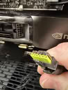
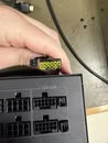
Source: Reddit
Add your own comment

169 Comments on ASRock's TempGuard Failed to Stop a PSU-Side Connector Meltdown on a $15,000 RTX PRO 6000 Rig

#1
Shrek
"The technician also says the sensor is mounted on the wrong side of the cable, on the ground line rather than the 12 V side it's supposed to watch, which would explain why it apparently never caught the rising heat in time."

?

The ground pins are just as susceptible to heating as the 12V pins.
Posted on Reply
#2
Athena
The technician also says the sensor is mounted on the wrong side of the cable, on the ground line rather than the 12 V side it's supposed to watch, which would explain why it apparently never caught the rising heat in time.
I see a recall in the near future...
Shrek"The technician also says the sensor is mounted on the wrong side of the cable, on the ground line rather than the 12 V side it's supposed to watch, which would explain why it apparently never caught the rising heat in time."

?

The ground pins are just as susceptible to heating as the 12V pins.
Maybe he read this...

www.igorslab.de/en/the-imbalance-of-current-flows-in-the-pc-why-only-certain-pins-of-the-12vhpwr-melt-and-via-ground-lines-on-detours-investigative/

Posted on Reply
#4
Shrek
AthenaMaybe he read this...

www.igorslab.de/en/the-imbalance-of-current-flows-in-the-pc-why-only-certain-pins-of-the-12vhpwr-melt-and-via-ground-lines-on-detours-investigative/
Charge conservation says as much current goes in as comes out (call it Kirchhoff's 1st law if you must)

Sure, one can have a 12V current and a 5V current and these combine at the ground wire, but here we have only 12V,
so the two currents (12V and Ground) must match as is confirmed by igor's measurements.

Posted on Reply
#5
lambda
They really need to stop putting lipstick on the pig that is this stupid connector.
Posted on Reply
#6
Wirko
ShrekThe ground pins are just as susceptible to heating as the 12V pins.
Exactly. I'm increasingly surprised every time I see pictures of an overheated connector with intact ground pins. This means that ground current takes some paths it shouldn't take, through PCIe slot and/or PC case, and given how PCs are constructed, mitigations could be impossible. Going to read Igor's article now.
Posted on Reply
#7
Shrek
Now it could be that the top sense pins are hindering cooling.
Posted on Reply
#8
Wirko
ShrekCharge conservation says as much current goes in as comes out (call it Kirchhoff's 1st law if you must)
We were taught about Kirchhoff's laws here, what's the name that Americans use?
Posted on Reply
#9
Shrek
Kirchhoff's laws the world round

But here we only need conservation of charge and not the loop law.
Posted on Reply
#11
Hecate91
More proof this connector just needs to be recalled already, or at minimum enforce a standard of load balancing and shunt resistors.
There are cases of the grounded side being melted also, and no part of the cable should get hot enough to melt or burn.
Posted on Reply
#12
Shrek
Does one really want to load balance?

Let's say one pin is suffering a voltage drop and so is heating up; does one really want to force it to then carry a full load?
Posted on Reply
#13
Hecate91

Buildzoid explained why the 12v2x6 connector is a downgrade from the initial 12vhpwr connector design, load balancing the connector into 3 separate 12V lines helps balance the load.
Although I assume this wouldn't be perfect either, not with how much power is going through a connector that at best should be limited to 300W, because of heat cycles possibly causing pins to lose contact.
Posted on Reply
#14
Shrek
I think everyone here agrees that a better connector is the preferred solution,
but I do recall how putting bridge rectifiers in parallel has the same load
balancing issue with the same (less than idea) solution of adding resistance.
Posted on Reply
#15
jh_berg
When will they admit that the 12VHPWR connector and its 12V-2×6 revision are a failure?
Posted on Reply
#16
Veseleil
This isn't funny anymore, it's rather sad. This damn connector needs to visit hell to meet its father, and stay there with him for the eternity.
Posted on Reply
#17
Vya Domus
Worry not if your 15000$ card catches fire Nvidia will happily sell you another one for 20000$ in a few months.
Posted on Reply
#18
Wirko
ShrekI do recall how putting bridge rectifiers in parallel has the same load
balancing issue with the same (less than idea) solution of adding resistance.
Another case, certainly familiar to DIY electronics fans, are power transistors in audio amplifiers. Bipolar transistors need these resistors (balancing is one of their roles but not the only one). MOSFETS don't need them, they somehow self-balance (something something temperature coefficient, I forgot). Here's an extremely parallel example:
Posted on Reply
#19
rusty caterpillar
lambdaThey really to stop putting lipstick on the pig that is this stupid connector.
Oh... but we gonna see that pig with lipstick for long time, they'll will put a wig on, eye shadow, even DLSS 5 if requires. The pig will be present at DLSS 6 launching.
Group prayer for 12v recall anybody??
Posted on Reply
#20
Shrek
WirkoAnother case, certainly familiar to DIY electronics fans, are power transistors in audio amplifiers. Bipolar transistors need these resistors (balancing is one of their roles but not the only one). MOSFETS don't need them, they somehow self-balance (something something temperature coefficient, I forgot). Here's an extremely parallel example:
Those 16 balance resistors are rated for 10W each, so one wonders how much power is lost to balancing in that 300W amplifier.
Posted on Reply
#21
Wirko
ShrekDoes one really want to load balance?

Let's say one pin is suffering a voltage drop and so is heating up; does one really want to force it to then carry a full load?
Yes, it's better with than without because you avoid the chain reaction that leaves only one or two pins carrying almost all current. But other protection mechanisms are necessary too, most certainly current measurement and limiting on each pin, and if limiting isn't possible, a safety shutdown should follow.

There's also a situation, improbable but possible, where ALL six +12V pins suffer a voltage drop of a similar magnitude. To protect against this, you need even more complicated solutions, which involve either a temperature sensor and overheating protection, and/or an additional voltage sense wire, which carries +12V with no current from the PSU to the GPU.
Posted on Reply
#22
BoggledBeagle
I have been proposing to make the connector more robust since more than 1,5 years ago.
BoggledBeagle in It's happening again, melting 12v high pwr connectorsLooking at the 12 tiny pins, why do not we have just 6 massive tabs instead? The overall size of the connector would be the same. There could be some cutouts on the plug connectors sleeves, and in the…
There is really no place for user error (installing worn cable, straining the plugs) and also a manufacturing error - as making the contacts inside the plugs too loose or from some soft easy to deform metal while using an extremely expensive GPU.

I wonder if some manufacturer, that really takes care to make the plugs properly - so that the contact tubes grip the pins really well, even exists today.
Posted on Reply
#23
Darmok N Jalad
Those with more electrical knowledge can maybe help me out, but what's the difference between this situation and say, a 600+W amplifier that's powered by a 12V line in an automobile? Those typically are fed off one 12V line and a ground. Are they not comparable, or is it just a matter of a larger gauge of wire doing the job?
Posted on Reply
#24
A Computer Guy
Sad a $15,000 GPU lacks the necessary protection circuitry in 2026.
Posted on Reply
#25
Raptor_i
How no one can force Nvidia to recall cards with this connector or use a new standard, we didn't have such issues with 3x 8 pins ... It's simple physics: high load over small pins = overheating :banghead:
Posted on Reply
Add your own comment
Nov 12th, 2026 19:06 PST change timezone

New Forum Posts

Popular Reviews

TPU on YouTube

Controversial News Posts