Sunday, August 30th 2026

NVIDIA Shuts Down RTX 5000 Power Limit Control OC in Latest Driver Update

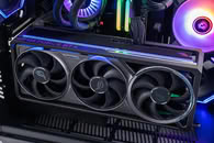
We recently reported on the open-source overclocking tool, mVolt+, unlocking power limit control on NVIDIA GeForce RTX 5000-series GPUs, allowing certain GPUs, like the RTX 5090, to draw up to 125 W of additional power and enabling significantly higher core clock speeds as a result. With the latest driver update 616.56, however, it seems as though NVIDIA has blocked the core power control functionality.

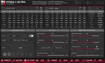
Based on reports from the Overclock.net forums, via Uniko's Hardware on X, any attempt to input any extra current results in a black screen, reminiscent of a driver crash. Reportedly, a beta build of Hydra 2.3 is still able to access its core power overrides on NVIDIA GPUs, even after the driver update. It's unclear if NVIDIA has intentionally blocked mVolt+ or if it's simply an untested combination of mVolt+ and the new NVIDIA driver causing an incompatibility.
Sources: Overclock.net, via Uniko's Hardware
Add your own comment

53 Comments on NVIDIA Shuts Down RTX 5000 Power Limit Control OC in Latest Driver Update

#26
kazuviking
RejZoRWe had graphic cards that pulled 600W in the past and they were powered by 3x 8pin connectors. Which each per specs only supports 150W.
The connector starts melting at 450W while the wire at 336W if its a lower end psu.
Posted on Reply
#27
Tess
RejZoRI don't understand how they developed such a dumb connector.
They selected it from a catalogue. I kid you not!
Posted on Reply
#28
pksmart_tech
Not surprised at all. The 16-pin connector on the RTX 5090 was already controversial. Allowing 125W more power on top of 500W+? That's a recipe for melted connectors and RMAs. NVIDIA is protecting themselves — and their hardware.
Posted on Reply
#29
kazuviking
pksmart_techNot surprised at all. The 16-pin connector on the RTX 5090 was already controversial. Allowing 125W more power on top of 500W+? That's a recipe for melted connectors and RMAs. NVIDIA is protecting themselves — and their hardware.
The connector can handle 600W if the pcb would be designed properly and not tied to the same power plane. For the 5090 having only 4 power phases on one pin would've completely solved it.
Posted on Reply
#30
Tess
kazuvikingThe connector starts melting at 450W while the wire at 336W if its a lower end psu.
Watts? I run my card at 400W occasionally. There's no melting. It's a $100 pos PSU 1200W. The wires get to about 45° at 400W - the connector to about 42°. That's right at the card. 3 inches back it's nearly 10° lower and 6 inches back it's barely over case ambience.

The wires and connector are rated for 600W, no?
Posted on Reply
#31
RootinTootinPootin
W1zzardThat doesn't let you bypass the power limit either, doesn't it?
On 4000 series nope, on RTX 5000 series depends on VBIOS..on the stock Astral vbios (performance) it can go beyond 600W, also works with FE version, saw a couple of guys using FE that went beyond the hard limit and got a huge performance uplift even by just a bit using melonvolt, there's no harm when you know what you're playing with, else not for NOOBS and with poor heart rates
Posted on Reply
#32
Arctucas
Sol_Badguy<SNIP

A single beefy connector and subsequent cable (say 14AWG wires) would be more difficult to bend and to route.

<SNIP>
14AWG fine stranded silicone insulated wire is very flexible, probably more so than the normal 18AWG cables supplied with a PSU.

At 15 Amperes per conductor; 4 x 14AWG conductors = 720 Watts for standard 8 pin PCI-E cable.
Posted on Reply
#33
kazuviking
TesselatorI run my card at 400W occasionally.
Through a single 8 pin?
TesselatorThe wires and connector are rated for 600W, no?
18awg is rated at 7A nominal and 18A in open air.
Posted on Reply
#34
_roman_
Nvidia gets their own article, when amd does it for my lying around powercolor 7800xt hellhound silently, no news.

just to say it again, it is not only nvidia who removes features from the firmware, amd does it also. i was lucky to find the source and checked it myself becuase i had 1 vs 1 the same card and modell of the 7800xt.
Based on reports from the Overclock.net forums
i think that was also my source but bear in mind you have to read 100 pages quite often for a few pieces of information.

See what i verified myself ages ago here: www.techpowerup.com/forums/threads/amd-removed-sensor-output-and-partly-access-to-the-powercolor-7800xt-hellhound-graphic-card-gnu-userspace-linux-kernel-radeon-9070xt.345680/

Note: I am well aware of whataboutism, etc. I believe the same standards should apply for any graphic card chip maker, not only nvidia. I am not interested in intel, as Intel gpus annoyed me for over 10 years, the driver quality was rubbish and the performance was rubbish. And it was not the userspace fault because I run for a while two gentoo notebooks over years.

-- i see the reason to segment the market, to upsell, sell you antoher nvidia graphic card.

-- it is kinda average joe sport to overclock, e.g. msi afterburner etc. Even amd has the overclock feature in the windows driver, ati had it also and nvidia also.

-- nvidia seems to think the connector is suitable for that power draw. and many cards show that it is a fact. Those few RMA do not matter as most grpahic cards only have a year warranty. Sometimes two years, later the card should get defective which increases repair costs and will cause more graphic card sales.
Sol_BadguyWhen in fact it was never about "solving the cable mess" because the official nVidia and its AIBs recommendation is to use the octopus adapter which keeps the same cable mess, the only difference is the mess doesn't start right at the edge of a GPU with a longer PCB, instead some cm further from the edge of a GPU with a shorter PCB.
Well done! So optical looks are definitely not the root cause for the changed power adaptor.

--

TRUE RMS Multimeters, Current clamp meters, etc. When you have real silicion probes they are very flexible, the cheap stuff which is not that flexible. the costs differences are minimal for silicion cables when you buy probes / measuring leads.
Posted on Reply
#35
Tess
Ah, I guess I misunderstood.
kazuvikingThrough a single 8 pin?

18awg is rated at 7A nominal and 18A in open air.
Ah, I guess I misunderstood. Oops. I got he part about "multi-phase" though - I think... The 5090 has a large multi-phase VRM (around 30 phases on the FE). If the PCB designers had routed the power so that only a limited number of VRM phases were connected to each individual pin (or small group of pins), then even if one pin had perfect contact and the others were poor, the maximum current that single pin could be asked to carry would be capped by the number of phases it feeds. The VRM controller already balances current across phases, so limiting phases per pin would automatically limit current per pin... was that what you were talking about?
Posted on Reply
#36
iameatingjam
TesselatorWatts? I run my card at 400W occasionally. There's no melting. It's a $100 pos PSU 1200W. The wires get to about 45° at 400W - the connector to about 42°. That's right at the card. 3 inches back it's nearly 10° lower and 6 inches back it's barely over case ambience.

The wires and connector are rated for 600W, no?
Yeah I'm confused by that comment as well. I normally don't like to run too far over 300w just incase, but when I got my new PSU and 12 6x2 cable, I wanted to test it out with furmark and got my 4090 pulling ~570w and did that for 15 minutes or so, keeping my fingers on the wires to see how hot they got, making sure one did not get noticeably more hot than the others.... yeah thats my manual clamp meter, lol.

Anyway, I don't think the issue is so bad, that every cable is going to melt if it hits rated values, more like there's no room for any weak links in the chain, which makes it very precarious.
Posted on Reply
#37
Tess
iameatingjamYeah I'm confused by that comment as well. I normally don't like to run too far over 300w just incase, but when I got my new PSU and 12 6x2 cable, I wanted to test it out with furmark and got my 4090 pulling ~570w and did that for 15 minutes or so, keeping my fingers on the wires to see how hot they got, making sure one did not get noticeably more hot than the others.... yeah thats my manual clamp meter, lol.

Anyway, I don't think the issue is so bad, that every cable is going to melt if it hits rated values, more like there's no room for any weak links in the chain, which makes it very precarious.
I think Kazu might be an engineer - at least they talk like that as well: short, highly contextual remarks which assume everyone knows more than they do (except other engineers) or will take the time to catch up. :D Minimum verbosity, maximum application.
Posted on Reply
#38
kazuviking
TesselatorIf the PCB designers had routed the power so that only a limited number of VRM phases were connected to each individual pin (or small group of pins), then even if one pin had perfect contact and the others were poor, the maximum current that single pin could be asked to carry would be capped by the number of phases it feeds.
Yep. Most of the oems used this on rdna 2 and 3 gpus where the 8 pins were connected to different phases. The 3090ti used this approach but since the connector is garbage and they used 2 pin per x phase it recently burned. No other reports so far.
Posted on Reply
#39
Sol_Badguy
Arctucas14AWG fine stranded silicone insulated wire is very flexible, probably more so than the normal 18AWG cables supplied with a PSU.
I'm comparing normal PSU cables 18AWG vs 16AWG there is a clear difference in wire thickness and flexibility.
I don't have 14AWG but extrapolating from the first two it's obvious it will be thicker and stiffer (some might like it that way).
ArctucasAt 15 Amperes per conductor; 4 x 14AWG conductors = 720 Watts for standard 8 pin PCI-E cable.
15A per wire is way too optimistic.
Look here:
www.jongerow.com/PCIe/index.html
14AWG isn't included but you can extrapolate from the jumps from 18 to 16 and 20 to 16.

It's not only the wire itself but also the connector's thermal density limits.
You're asking the plastic housing to handle the heat from 1.5x the maximum load (10A from the second table).

EDIT. By the way you said 8 pin PCIe. But then you wrote 4 wires which is the EPS, the PCIe has 3x 12V wires.
Posted on Reply
#40
_roman_
When you solder or desolder a connector you will learn and see instantly how big pins and pcb copper planes act as a heatsink. it is also a fail on the pcb to not include passive cooling wiht some air movements, there are fans in the area anyway.
Posted on Reply
#41
Arctucas
Sol_BadguyI'm comparing normal PSU cables 18AWG vs 16AWG there is a clear difference in wire thickness and flexibility.
I don't have 14AWG but extrapolating from the first two it's obvious it will be thicker and stiffer (some might like it that way).

15A per wire is way too optimistic.
Look here:
www.jongerow.com/PCIe/index.html
14AWG isn't included but you can extrapolate from the jumps from 18 to 16 and 20 to 16.

It's not only the wire itself but also the connector's thermal density limits.
You're asking the plastic housing to handle the heat from 1.5x the maximum load (10A from the second table).

EDIT. By the way you said 8 pin PCIe. But then you wrote 4 wires which is the EPS, the PCIe has 3x 12V wires.
Right, should be three +12V.

www.playtool.com/pages/psuconnectors/connectors.html#pciexpress8

Mini Fit Jr. 9A max per terminal. www.molex.com/content/dam/molex/molex-dot-com/en_us/pdf/datasheets/987651-8272.pdf?inline.

So, 27A x 12 V = 324W for the connector.

However, the ampacity of the conductors is still true. We just need better (higher ampacity) connector. Like TE Commercial Mate-N-Lok. www.te.com/en/plp/commercial-mate-n-lok/X25kx.html
Posted on Reply
#42
Sol_Badguy
ArctucasHowever, the ampacity of the conductors is still true. We just need better (higher ampacity) connector. Like TE Commercial Mate-N-Lok. www.te.com/en/plp/commercial-mate-n-lok/X25kx.html
I'm getting "we need to invent this and that" fatigue.
Why not just use two 8 pin EPS and be done with it?
Do you have an interest in keeping the PCB as short as possible and just one connector/cable?
Two 8 pin EPS would only be for the 4090 and 5090 so the other cards can work fine with just one.
Well the 5080 is in the gray zone a bit, a default 360 W one can definitely be okay, there is the PCIe slot as well, but a 400 W or greater one is pushing it.
www.techpowerup.com/review/pny-rtx-5080-slim-oc/41.html
I see two with 450 W there, the Gigabyte Gaming and ASUS Noctua.
Yeah definitely two connectors for those.

We already have more than adequate tools available, there is no need to overcomplicate things, in fact the monitoring/protection gadgets that were developed as a remedy for this fire hazard connector are a symptom of overcomplication. Proper connectors would make these gadgets redundant.

But nobody would make any money using tried and tested, reliable connectors.
In order to exploit the consumer you have to make him chase the next best thing (invent the problem then sell the solution), the ultimate protection, the next gadget will surely be unbeatable, the next sci-fi PSU will phone the fire departament by itself if the pins go unbalanced.
And so on, all of this BS is anti-consumer maxxing.
Posted on Reply
#43
kazuviking
Sol_BadguyWell the 5080 is in the gray zone a bit, a default 360 W one can definitely be okay, there is the PCIe slot as well, but a 400 W or greater one is pushing it.
It should enough as the pcie slot can be used for memory, misc voltages and fans. Yes this bites you in the ass if using 1-4X risers.

EPS is only rated for 235W continuous for safe operation. But even with that pushing 300W through that connector is not an issue.
Posted on Reply
#44
Arctucas
Sol_BadguyI'm getting "we need to invent this and that" fatigue.
Why not just use two 8 pin EPS and be done with it?
Do you have an interest in keeping the PCB as short as possible and just one connector/cable?
Two 8 pin EPS would only be for the 4090 and 5090 so the other cards can work fine with just one.
Well the 5080 is in the gray zone a bit, a default 360 W one can definitely be okay, there is the PCIe slot as well, but a 400 W or greater one is pushing it.
www.techpowerup.com/review/pny-rtx-5080-slim-oc/41.html
I see two with 450 W there, the Gigabyte Gaming and ASUS Noctua.
Yeah definitely two connectors for those.

We already have more than adequate tools available, there is no need to overcomplicate things, in fact the monitoring/protection gadgets that were developed as a remedy for this fire hazard connector are a symptom of overcomplication. Proper connectors would make these gadgets redundant.

But nobody would make any money using tried and tested, reliable connectors.
In order to exploit the consumer you have to make him chase the next best thing (invent the problem then sell the solution), the ultimate protection, the next gadget will surely be unbeatable, the next sci-fi PSU will phone the fire departament by itself if the pins go unbalanced.
And so on, all of this BS is anti-consumer maxxing.
Two EPS should handle the current generation of cards, but...

Having watched the power levels evolve over the last 20+ years, who is to say that will be adequate a few years from now?

A little 'future-proofing' would be a good idea, no?
Posted on Reply
#45
Darmok N Jalad
SiliconSeraphKinda surprised no one has done this before tbh, sounds like an honestly great idea. The thing is though, what's saying that fill-in-the-blank standard of hardwire cable couldn't be poorly designed, as the current melt-prone connectors are? Sure it's splitting hairs, but it's something to keep in mind perhaps. Still, great idea!
Well, if the OEM can't spec the right cable for their own card, then they deserve the outcome. Right now, we're in this no man's land of blaming the card, the connector, the cable, the user, the PSU. Now we're down to making one proper connection at the base of the PSU, which shouldn't be as susceptible to bending and stress and such.
Posted on Reply
#46
kazuviking
Darmok N JaladRight now, we're in this no man's land of blaming the card, the connector, the cable, the user, the PSU.
Corsair was known for shipping garbage cables with their psus. The connector have insane levels of tolerances to the point where user error is bound to happen 95% of the times. J2C demonstrated it that even a tiny tug dislodged the connector where it can cause burn. Then there is thermal cycles which caused the connector to dislodge over time.

You either hotglue the connector in place or solder the wires tot he gpu and psu.
Posted on Reply
#47
Athena
pksmart_techThis is the new normal. NVIDIA is treating overclocking as a security risk — or at least a warranty risk. Expect future drivers to lock down even more. The era of "free performance" through software tweaks on NVIDIA cards may be coming to an end.
The problem is, that say they overclocked it to the max with however high voltage that was needed, but that damaged or limited the life of the card, and those people turn around and sell the card, and it fails down the road, the OEMs are on the hook for warranty replacement

That is why it should be locked down from crazy high voltages
Posted on Reply
#48
MikOnTopGG
I don't understand why they implement this feature and then take it down. I mean, I understand that some people that don't really know what they're doing can quickly mess their GPU up, but this was a solid tool for enthusiasts and OC geeks.
AthenaThe problem is, that say they overclocked it to the max with however high voltage that was needed, but that damaged or limited the life of the card, and those people turn around and sell the card, and it fails down the road, the OEMs are on the hook for warranty replacement

That is why it should be locked down from crazy high voltages
The thing with the warranty risk makes sense though. Although, still, it should be directed towards the more advanced users.
Posted on Reply
#49
Arctucas
Use 610.88 or wait for mvolt to be updated to work with the new driver.
Posted on Reply
#50
rusty caterpillar
TesselatorAh, I guess I misunderstood.

Ah, I guess I misunderstood. Oops. I got he part about "multi-phase" though - I think... The 5090 has a large multi-phase VRM (around 30 phases on the FE). If the PCB designers had routed the power so that only a limited number of VRM phases were connected to each individual pin (or small group of pins), then even if one pin had perfect contact and the others were poor, the maximum current that single pin could be asked to carry would be capped by the number of phases it feeds. The VRM controller already balances current across phases, so limiting phases per pin would automatically limit current per pin... was that what you were talking about?
I think you can compare 3090Ti with any 5000 and you'll see the difference. Power delivery on PCB.
I know only one 3090 Ti melted after all this time.
iameatingjamIts not just that its a bad connector, there's not even any kind of load balancing or any other kind of protection on the card itself like there should be for something with so much power running through such small cables and questionable mating mechanisms. Why do the connectors have to be so small? Even if it was a little bigger, with thicker cables, one reliable mating mechanism, and the right measures built into the card to help avoid problems (if necessary, like it is now) and or with some more safety margin built in. I am 100% certain nvidia is capable of producing a single, simple cable that can deliver 600w without any problem.
But it is a bad connector and yes there isn't a load balancing.
They like it that way.
For the same reason 5000 PCB lacks fuses and enough shunt resistors, power delivery on the PCB is designed with one on FE and sometimes 2 planes on others but no per-path current monitoring.
3090 Ti 12 VHP non FE had 3 planes monitored on the PCB.

On short: PCB + connector = short life GPU on users wallet.
Posted on Reply
Add your own comment
Nov 19th, 2026 00:53 PST change timezone

New Forum Posts

Popular Reviews

TPU on YouTube

Controversial News Posts