Tuesday, December 5th 2023

Intel "Emerald Rapids" Die Configuration Leaks, More Details Appear
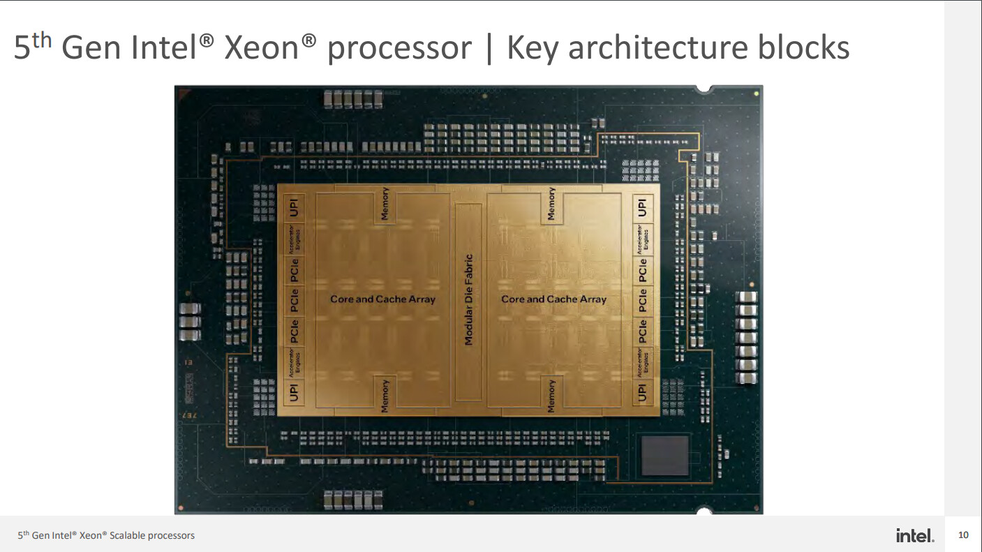
Thanks to the leaked slides obtained by @InstLatX64, we have more details and some performance estimates about Intel's upcoming 5th Generation Xeon "Emerald Rapids" CPUs, boasting a significant performance leap over its predecessors. Leading the Emerald Rapids family is the top-end SKU, the Xeon 8592+, which features 64 cores and 128 threads, backed by a massive 480 MB L3 cache pool. The upcoming lineup shifts from a 4-tile to a 2-tile design to minimize latency and improve performance. The design utilizes the P-Core architecture under the Raptor Cove ISA and promises up to 40% faster performance than the current 4th Generation "Sapphire Rapids" CPUs in AI applications utilizing Intel AMX engine. Each chiplet has 35 cores, three of which are disabled, and each tile has two DDR5-5600 MT/s memory controllers, which operate two memory channels each and translating that into eight-channel design. There are three PCIe controllers per die, making it six in total.
Newer protocols and AI accelerators also back the upcoming lineup. Now, the Emerald Rapids family supports the Compute Express Link (CXL) Types 1/2/3 in addition to up to 80 PCIe Gen 5 lanes and enhanced Intel Ultra Path Interconnect (UPI). There are four UPI controllers spread over two dies. Moreover, features like the four on-die Intel Accelerator Engines, optimized power mode, and up to 17% improvement in general-purpose workloads make it seem like a big step up from the current generation. Much of this technology is found on the existing Sapphire Rapids SKUs, with the new generation enhancing the AI processing capability further. You can see the die configuration below. The 5th Generation Emerald Rapids designs are supposed to be official on December 14th, just a few days away.
Sources:
European Southern Observatory Presentation, via @InstLatX64 (X/Twitter)
Newer protocols and AI accelerators also back the upcoming lineup. Now, the Emerald Rapids family supports the Compute Express Link (CXL) Types 1/2/3 in addition to up to 80 PCIe Gen 5 lanes and enhanced Intel Ultra Path Interconnect (UPI). There are four UPI controllers spread over two dies. Moreover, features like the four on-die Intel Accelerator Engines, optimized power mode, and up to 17% improvement in general-purpose workloads make it seem like a big step up from the current generation. Much of this technology is found on the existing Sapphire Rapids SKUs, with the new generation enhancing the AI processing capability further. You can see the die configuration below. The 5th Generation Emerald Rapids designs are supposed to be official on December 14th, just a few days away.
28 Comments on Intel "Emerald Rapids" Die Configuration Leaks, More Details Appear
I should explain in more detail. CPU power is actually active power + static power. Active power is when the transistor is active and switching activity is going on. Static power is leakage. There's a crossover point.
Simply put the tradeoffs are like this:
1. Lower voltages at high frequencies, larger area.
2. Higher voltages, much lower leakage.
This table illustrates it very well: www.realworldtech.com/includes/images/articles/iedm10-10.png?x97168
Let's look at Intel's 32nm process. There's High VT and Low VT. Low VT NMOS Idsat* 1550 ua/um with 100 ua/um leakage, while High VT NMOS is
1357 ua/um Idsat with 10ua/um leakage. This is just one aspect. The Low VT can drive higher current and switch faster, but leaks more, while for High VT it's the opposite. They can further this by design differences like P and E cores.
At laptop power levels, and especially like Ultrabook designs where every component is chosen for lower power, leakage power becomes significant, because that's an unchanging level regardless of load. Before Power Gating was introduced(with Nehalem) where certain sections of a circuit can be turned off to near-zero levels, they would clock gate, but still tons of leakage power.
So really you want a transistor that does better on low, plus ultra low leakage, which is basically what laptop chips are compared to desktop ones. For desktops, since the system is using 30W at idle anyway, cutting 5W CPU idle in half doesn't matter if you reduce peak frequency by 10%.
The way CPUs run nowadays aren't off and on. They go through multiple power and frequency levels as well. Some may be bursty enough that it doesn't even reach the max frequency since it happens so fast. The LP E cores primary purpose is to keep the compute tile off guaranteed while handling minimal tasks. I would think the chip is clocked closer to 1GHz than 2GHz, which is more than plenty enough for video playback, and in other cases like web browsing where more performance is required for a short amount of time, keep the components on a close leash so it actually powers down and hands back to the LP E cores when the demand goes lower again.
I can tell you on my system you need to do a lot of work to keep the CPU at a lower power state, and from what I hear they regressed post-Icelake. On Icelake, for some reason you can get 25 hours(30-50% over predecessor) screen-on idle but only 10 hour(same) battery life. So even that chip has a harder time keeping the cores off.
*Idsat means Current at saturation, ie when it's at max. VT stands for Threshold voltage, the point when transistors turn on.
So the same chip can be very efficient in one use case and inefficient in another, even if the type of work is the same but the load changes.
Low VT transistors are faster because the point where transistors turn on are lower and easier. The sacrifice is increased leakage current.
In addition, there's this: images.anandtech.com/doci/15967/N1.png
For lower power, you want a steeper curve, while for higher clocks you want the opposite. This is the reason why AMD mobile chips are ahead of Intel's at lower power, but it crosses over and is opposite at higher power levels. Intel 4 and Meteorlake looks to make the curve steeper based on preliminary data.
That graph makes my point a bit confusing, but what I mean is that the steeper curve allows for higher performance at lower power envelopes, but as you increase clocks and power, it crosses over and the products with a steeper curve ramps up in power so much more so that despite the early advantage, it'll end up using more power after that point. If you see rare comparisons of power/voltage/clock comparisons of laptop and desktop chips, you see just that. Mobile chips need more voltage to reach the same frequency.
If you read the Realworldtech articles, then you'll also see the lower leakage transistors have a lower drive current limit so there's a lower clock speed floor too. You can't just keep increasing voltage, not only it'll increase power dramatically, it might just fail anyways.