Monday, August 31st 2026

Modders Bypass RTX 5090's Melting Connector Issue by Soldering Wires Directly to the PCB

Brazilian YouTube group TecLab has bypassed the RTX 5090's notorious melting problem in the most direct way possible. The group removed the 16-pin connector from the equation entirely and soldered power wires straight onto the PCB. The demonstration used a Galax RTX 5090D HOF OC LAB XOC, an extreme-overclocking variant with two 16-pin inputs and a custom BIOS rated for up to 2,000W, far above the 575W TDP of a standard RTX 5090. TecLab framed the mod as a sarcastic jab at NVIDIA, saying that enthusiasts are tired of hearing about connectors melting and that they wanted to show how it should have been done from the start.

The team stripped the card's stock cooler entirely, running the bare GPU under an industrial liquid chiller with two loosely mounted fans for extra airflow. Two adapters converted standard 16-pin PSU cables into bare wires, which were then soldered directly onto the connector traces on the board. No temperature readings were shared, but a roughly 50A draw on the 12V rail put the card at around 600W during testing, and it booted and ran benchmarks without issue.
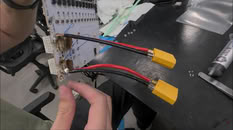
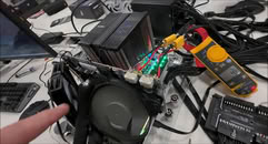
Melting 16-pin and 12V-2x6 connectors have plagued the RTX 5090 since launch. We have reported several such confirmed cases over the past year despite NVIDIA's redesigned connector geometry. Bypassing the connector is clearly not something regular owners should attempt on a nearly $5,000 card, and it doesn't address the underlying current-imbalance issues tied to the 12V-2x6 standard itself. Still, a soldered PCB connection outlasting NVIDIA's official fix says plenty about how unresolved this problem remains after all this time.
Source: TecLab on YouTube
Add your own comment

24 Comments on Modders Bypass RTX 5090's Melting Connector Issue by Soldering Wires Directly to the PCB

#1
Dragam1337
This sh1tty connector should obviously never have been used in the first place, and a couple of big fat wires seems the obvious solution.
Posted on Reply
#2
MikOnTopGG
Dang these guys are amazing! Yeah that connector is such a problem.
Posted on Reply
#3
N/A
It should be a mega-fit connector with a pitch of 5.7mm and 10AWG. Keep the 12 6x2 pins, just make it mega... also on the power side if it's modular...
Posted on Reply
#4
Dragam1337
N/AIt should be a mega-fit connector with a pitch of 5.7mm and 10AWG. Keep the 12 6x2 pins, just make it mega... also on the power side if it's modular...
No, cause as long as nvidia don't add any sort of power balancing, you can have all the power going through a single wire, even if you do size the connector up. Simple solution is only using 2 massive wires. Power and ground. Nvidia can't fack it up then.
Posted on Reply
#5
wNotyarD
I'd say calling TecLab a "YouTube group" is belittling what they did and still do for the overclocking community. If anything, just bypassing the 12V-2x6 connectors falls very short of other stuff they used to do.

Their zombie cards were quite the stuff!
Posted on Reply
#6
Hecate91
"Melting 16-pin and 12V-2x6 connectors have plagued the RTX 5090 since launch."
The 16 pin connector has plagued every card with it at 300W or more, the 5090 melts more and the connector should have never been standardized.
A minimum should've been fuses on the PCB, with power balancing and per pin detection.
Posted on Reply
#7
Dragam1337
Gotta say, im still somewhat certain that nvidia made this connector to make sure that people upgrade, rather than staying too many years on the same gpu...
Posted on Reply
#8
Wirko
What are those orange connectors, they look like XT60?
Posted on Reply
#9
ThomasK
wNotyarDI'd say calling TecLab a "YouTube group" is belittling
That's the usual when referring to us 3rd world country folks.

Anyway, the connector is plagued and Nvidia of all companies should've known better.
Posted on Reply
#10
ISSEnterprise
Someone offered a radical 'Solution' years before: the GPU should have its own power supply built-in so it can use the power cord to charge from the wall.
Posted on Reply
#11
Crackong
As we have mentioned few years before.
Since the power plane on the RTX card is just one big chunk of 12V
The best solution is always 2 wires

Posted on Reply
#13
N/A
Or they could use busbar clamps and then I wouldn't have to look at ugly soldering. I meant really sloppy, where are my smooth cones.
Posted on Reply
#14
JustBenching
Dragam1337Gotta say, im still somewhat certain that nvidia made this connector to make sure that people upgrade, rather than staying too many years on the same gpu...
Why? They don't offer RMAs anymore?
Posted on Reply
#15
john_
It’s incredible that this connector hasn't been pulled from the market. But I suppose someone convinced government departments that you can't just recall hundreds of millions of cards.
Posted on Reply
#16
kazuviking
Wirkothey look like XT60
XT120 as XT60 is only rated at 30A cpntinous.
Hecate91with power balancing
Nvidia forbidden oems of adding anything like that. Its our way or no gpus from us in the future.
Even phase balancing on the pins wouldve helped a lot. Having only 4 phases on a pin wouldve limited the per pin current to 100w and no matter what it coulnt draw any more from a single pin.
Posted on Reply
#17
Prima.Vera
LOL on those welds :laugh: :laugh: :laugh:
Posted on Reply
#18
docnorth
No big deal, it's like connecting a 60cm oven in the kitchen... :slap:
Posted on Reply
#19
b1k3rdude
Prima.VeraLOL on those welds :laugh: :laugh: :laugh:
Indeed, I appreciate they are willing to do this to a £4k card, but the soldering could and should have have been a LOT better..
Posted on Reply
#20
Grimling
JustBenchingWhy? They don't offer RMAs anymore?
Not for any connector issues!
Asus for example denies any RMA for melted Connectors.
People go to repair shops to get a new connector on their cards.
Posted on Reply
#21
Dorek
Mine didnt burn but the adapter dongle broke on its own being hooked up to the rtx 4080 for years.
Posted on Reply
#22
LabRat 891
CrackongAs we have mentioned few years before.
Since the power plane on the RTX card is just one big chunk of 12V
The best solution is always 2 wires

Agreed. I've been considering making some custom +12VHPWR/+12V2x6 cables with ultra flexible silicone welding lead.
kazuvikingXT120 as XT60 is only rated at 30A cpntinous.
IIRC, XT90s were used, according to other articles. Only 40-45A Continuous rated but, higher safety margin than +12VHPWR/+12V2x6.
kazuvikingNvidia forbidden oems of adding anything like that. Its our way or no gpus from us in the future.
Even phase balancing on the pins wouldve helped a lot. Having only 4 phases on a pin wouldve limited the per pin current to 100w and no matter what it coulnt draw any more from a single pin.
Cost. -and, I'm pretty sure this connector was designed to wear out and mitigate their new products competing with old.
It's just that, someone screwed up in engineering it to last 'just beyond warranty' :laugh:
Prima.VeraLOL on those welds :laugh: :laugh: :laugh:
Kinda love it. "Look how crappy of a solder job this is, and it's still better than the factory connector"
Posted on Reply
#23
close
b1k3rdudeIndeed, I appreciate they are willing to do this to a £4k card, but the soldering could and should have have been a LOT better..
That's 80ish Amps going through that solder points on each of the pairs, better be just an esthetic issue.
Posted on Reply
#24
user556
Sure, it can always look tidier but the soldering is fine. There is good wire length within the curled copper plates. The copper plates run the full length of the plug pins on the PCB. The wires are fully inserted in the solder nubs of the yellow connectors.
Posted on Reply
Add your own comment
Nov 22nd, 2026 00:22 PST change timezone

New Forum Posts

Popular Reviews

TPU on YouTube

Controversial News Posts