Sunday, September 13th 2026

ASRock's TempGuard Failed to Stop a PSU-Side Connector Meltdown on a $15,000 RTX PRO 6000 Rig
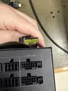
A repair shop technician has reported another melted 16-pin power connector on an ASRock Taichi TC-1650T PSU, paired with a $15,000 NVIDIA RTX PRO 6000 Blackwell Workstation Edition GPU. The former ships with native 12V-2x6 cables carrying ASRock's own NTC temperature sensor. According to the technician's Reddit post, the connector failed catastrophically on the PSU side and melted into the socket itself, even though both ends of the cable were fully seated. The GPU reportedly survived, and the damage was confined to the power supply side. The technician also says the sensor is mounted on the wrong side of the cable, on the ground line rather than the 12 V side it's supposed to watch, which would explain why it apparently never caught the rising heat in time.
ASRock added the NTC sensor and TempGuard system to its 12V-2x6 cables specifically to shut a system down before a connector melts. This time the system failed to catch the rising temperatures, but it has worked in the past. TempGuard reportedly caught a shunt-modded RTX 5090 pulling over 1,300 W, saving its power connectors from melting. On the flip side, this isn't the first time this exact GPU and PSU pairing has run into trouble either, as a similar melting incident on the same combo surfaced back in March. If the sensor placement is really off on at least some cables, that's a bigger concern than one bad unit, especially when paired with a card that costs as much as a used car.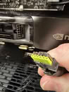
Source:
Reddit
ASRock added the NTC sensor and TempGuard system to its 12V-2x6 cables specifically to shut a system down before a connector melts. This time the system failed to catch the rising temperatures, but it has worked in the past. TempGuard reportedly caught a shunt-modded RTX 5090 pulling over 1,300 W, saving its power connectors from melting. On the flip side, this isn't the first time this exact GPU and PSU pairing has run into trouble either, as a similar melting incident on the same combo surfaced back in March. If the sensor placement is really off on at least some cables, that's a bigger concern than one bad unit, especially when paired with a card that costs as much as a used car.


169 Comments on ASRock's TempGuard Failed to Stop a PSU-Side Connector Meltdown on a $15,000 RTX PRO 6000 Rig
Loose connectors just burn out. That is a very common electrical failure. The reason is mechanical - too low contact force leading to too small contact area leading to too high current density which means too high heat production.
You do not approach a burned out connector hypothetising about complex balancing circuitry missing or other crazy stuff, you just think: aha, this connector was too loose and that it why it burned out. You do not approach a traditional bulb not producing light anymore thinking aliens hit it with a death beam, but thinking it happened because the filament just broke or melted due to mechanical shock, age or too high voltage - because that is how normal bulbs break.
Again, and again: Connectors burn out because they get too loose. PERIOD!
Also, power delivery connector chosen is one of points of device electrical design. Choosing wrong makes device design wrong.
Again, and again: Connector design is the problem.
Sheesh
In the last 5 years I had 3 mobos fail on me, 2 of them where RMAed. In the meanwhile my 12vhp cable has been working flawlessly nonstop, but somehow if I buy "ngreedia with taht melting houseburning connector" im an idiot. Okay
However, electrical design of RTX 5x00 series is also junk.
Also, regardless of design, it is stupid idea to send 600W through one connector in tight space prone to heating.
Lets be clear here, the Connector is FINE! IT JUST WORKS!
All these reported failures (most of them are fake and AI-Slop of course) are only happening, because people are lacking the necessary intelligence to use the Connector correctly!
Its either user Error (very likely), or a $5.27 trillion Companies incompetence to design a Connector (practically impossible).
The hot, 12V DC pins are moving the current. WE all know how big pins when you want to desolder, need a lot of head. The reason why the cheap shit 30W Ersa soldering iron did not work and i bought a ERSA RDS 80 wiht lots of soldering heat.nope.
I brought the soldering iron example on purpose. You can verify it yourself. how long does it take to heat
I do not own a hot air station, but it makes sense to use a small nozzle with lots of hot air to solder components.
A infred thermometer could also show you that, how electronics have high heat spots and lower one. No money and no will to buy a thermal camera which may suit this purpose better.
--
edit: Measuring on the GND pins is nonsense. Igor and other already claimed that the current does not flow back 100%. It would be different when the hole pcie slot were only optocouplers.
-- typical asrock fail, i am not surprised.
-- the power supply is not according to specification. When you can draw more power as specified you need to have proper connectors. Limit it to e.g. 600 Watts and use a 600Watt connector.
note: that stuff is such obfuscated that finding a spec paper, and all the stuff is too time consuming. fill in the number which is correct 600 Watts , 650 Watts, etc.
I do not know what the reference of 1300 Watts is in the text. Was 1300 Watts used in this scenario for the 12 Volt "high power" (lol) v1 or v2 "600" Watt connector?
I do not consider the power strip with around 3.6kW as high power. Or my hair dryer which has around afaik 1200 Watts as high power.
High power are 30 Amps @ 400V AC 50 hz. not 600 Watts
My water kettle has for sure more than 600 Watts. ... Is it high power?
Igor failed to explain Kirchhoff. It seems you did not grasp yet Kirchhoff, although i tried to explain it to you in personal message several weeks ago.
You may read the kirchhoff laws first. Basics. Igor had a very low quality german article about it. The sum of currents are always zero, the sum of voltages is always zero -> read yourself kirhchoff law - wikipedia has a low quality text article about it.
A PSU has several GND planes and different connectors with GND. You may cut all the other GND wires on the psu than this Asrock cable will work correctly, when only the 12V high power connector has the only gnd wires left.
TLDR: Kirchhoff Laws
They will totally cut the heat out of equation, but I guess you need a PHD in electrotechnics for that, that a 5 trillion company cannot afford.
There are a lot of GND pins on a power supply unit on multiple connectors, not only the 12V high power oneShrek asked me in personal message weeks ago and i tried to explain
what DELTA means and what kirhchoff means
with references to my school books in german / other german technical electronics books + isbn numbers
I do admit, i did not read the last pm than.
English call it kirchhoff law, as i had to look it up for Shrek at that time. Wikipedia page exists.
I will not post any personal message in public. i can mention it but i will not post it
-- The school i attented was 5 years and not everyone grasped it. I myself had to read it several times as a teenager and apply it. When you do not grasp kirchhoff you assume it wrong. I will not question core principles. I have a True rms current clamp meter multimetrter and i verified it anyway on my car anyway 20 years ago. A Diesel Car is a nice example, alternator, generator, battery, charger, etc..
The current limitations were told already over and over again. Kirchhoff Law were also told over and over gain.you usually thermal couple power electronics. It has a reason why power electronics are on the same heatsink. So they are on the same thermal field of the specification characteristics.
mosfet usually it is enough to thermal couple those. that is also the reason why some need an insulator between the power electronic component to the heatsink.
The RDS on value also matters with other characteristics. Do not ask me for specifics, I did not deal with that stuff for 20 years by now. -- ohm law also applies
When you thermal couple those, the component which gets hotter changes characteristics is prevented by thermal coupling those. With its own heatsink you would have a runaway component.The inefficency of Bipolar transistors are a given and well known fact
The inefficiency of Class A amplifier is a given
I have a reason why i bought a class D amplifier, a ADAM T8V studio monitor. Another word for an active speaker with flat line input to output frequency speaker.
Those bipolar transistor designs are technology from year 1980 in my point of view and some fancy marketing stuff.
-- we should stick to the core topic, the 12 V high power connector, gen 1 and gen2I only watch from far away.
Usually you have 1 Farad 12V DC capacitor in the car audio system. 1 Farad is very big capacitor to buffer high demand spikes.
The wires are bigger and use a different connector.
I think around 1996 someone explained me in school about the "skin effect". Power electronics sometimes behave similar as the high frequency field which is more my field of expertise.
You need to look into physics, solid core, vs not solid core, how many small wires in a cable, etc.
physics / power electronics / high frequency electronics will answer that. That is a lot of different materials to read.
I am sure there are books with tables, spec sheets etc, which explain it.
I do not know any car audio system which usees the intel / nvidia / whatever else 12V high power connector.
-- Those car amps, i am not sure, are peak watts. That is also a rabbit hole to read and explain. Someone else should elaborate and correct my statement aobut peak power in speaker, vs amplifier, vs efficiency of amplifiers in audio equipment etc. That will be a lengthy text where most likely most will skip reading frustrated at some point
When we talk about efficiency, i think i remember 25% for class a amplifiers efficiency. What wirko showed with teh year 1980 bipolar transistor design.
-- Do not be early adopter. I bought on purpose AM5 in 2023 and not earlier. Let other tests and taste the green bananas which slowly turn yellow or tasty, or which are turning bad.
I do not know how many hair dryers I saw melted and destroyed bevause overheating whem pushed to work hard.
Simply, it is lot of watts, so it generates lot of heat, so lifespan becomes shorter... Bad choice.
And if it is unavoidable, then very strict QC, lare safety overheads and seriously overengineered connectors should be mandated.Imagine how much more expensive it would be, how much more stress to MoFSETs would be, how much more tracing it would need...
Also, nVidia, AMD and Intel could forget about improving their efficiency, instead they could keep adding moar watts until we are back at 1 kW again... We do not want that...
Finally, backward compatibility would be gone... We can not move on from ATX standard for years, let alone switch to completely different architecture...
MOSFETs are positive temperature coefficient. Meaning their resistance rises as they heat up. Here we get the opposite effect where the hotter parts take less of the load and thereby naturally balances.
Copper wire (all metals, including the connector contacts) is positive temperature coefficient, just like MOSFETs. Therefore adding resistors is pointless. The reason for adding any resistors is as a detector, not a balancer.
PS: The reason for the rather high value of 10 ohms for that audio amplifier is because that makes the transistors exceptionally good current control then. Very good for output linearity.
faulty designuser error.And this is only a tip of a huge pyramid made of RTX GPUs that have:
- partially melted but are not causing black screens, thus users are unaware of the situation,
- melted but cases were not published or disclosed,
- melted but sold to other owner, as the price of the card multiplied (repairing connector is pretty cheap compared to getting new card).
Unfortunately, TPU does not cover all the published cases.
This connector and badly designed power delivery rail in RTX 4080/4090/5000 series is golden eggs laying duck for NorthridgeFix.
I measured it with direct current clamp meter measuring separatelly live and ground wires and the result was clear - it is not a coincidence that most of the time live connector part melts.
Some of the photos from the measurement are in my survey thread (not a comparison between the in and out current), in which I attempted to collect some useful information about melted cable incidents, but which unfortunately did not cause much traction.
At this stage of things, since manufacturers are doing nothing serious, the best solution is cut the plugs off the cables and solder the cables at both ends.
Well, there is also supposed to be the Segotep TitanLoad but I've not yet seen anyone review it. www.techpowerup.com/343694/segotep-claims-titanload-12v-2x6-cable-lowers-temperatures